- Products
- Compressors & Assemblies
- Compressors
- Fully-hermetic
- Scroll
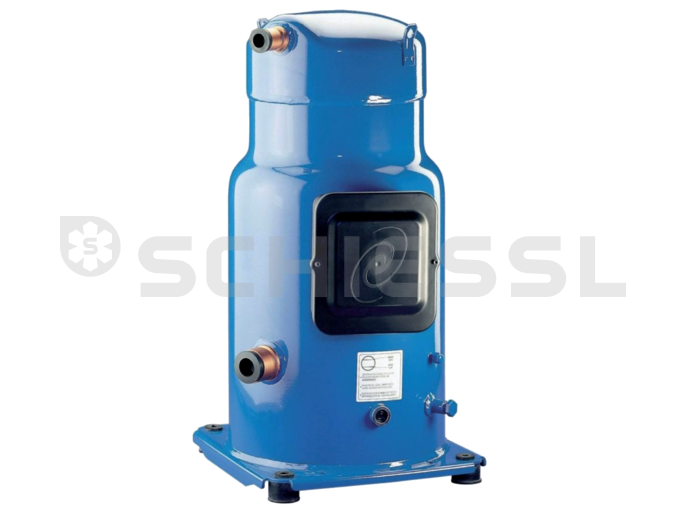
- Danfoss Scroll compressor SZ120-4 solder 400V
Danfoss Scroll compressor SZ120-4 solder 400V

Description
In Danfoss Performer® scroll compressors, compression takes place between two scroll elements positioned in the upper area of the compressor housing above the motor (see diagram). The intake nozzles on the compressor are located in the lower area of the housing. The intake gas enters the ...
In Danfoss Performer® scroll compressors, compression takes place between two scroll elements positioned in the upper area of the compressor housing above the motor (see diagram). The intake nozzles on the compressor are located in the lower area of the housing. The intake gas enters the large volume compressor housing and is guided through the lateral openings in the motor plate and across the motor. Any oil droplets that are also pulled through are separated from the intake gas and deposited into the oil sump. The gas that is guided across the motor cools the motor and is then guided into the scroll unit.
The compressor system consists of 2 scrolls (spirals), an orbital scroll and a fixed scroll. The figure on page 5 explains the compression process. The upper spiral containing the pressurised gas outlet remains static while the lower spiral performs an eccentric motion. Both spirals are held at a fixed angle to one another (180 °) using a special drive unit. When the lower spiral moves into the upper spiral, a crescent shaped compression area is created, the volume of which reduces towards the centre of the spirals. Throughout the steady working process of the two spirals moving inside one another, suction, compression and output takes place. Three rotations are required to fully compress the volume, producing consistent and gentle compression. A check valve is located at the outlet of the scroll. This protects the compressor from backflow when switched off. The pressurised gas nozzle is located on the side towards the top of the compressor housing.
Accessories / Replacement parts
-
Crankcase heater
-
Refrigerator oil
-
Sound insulation hood
Technical data
Siehe Erläuterung 1
R134a = 6.18 kW
R407C = 8.98 kW
Note:
- Previously sold by Danfoss as a tandem compressor; currently available as upgrade set: 2 pcs compressor + adapter set + oil equalisation / see accessories
Motor voltage code 4 = rated voltage 400 V - 3 - 50 Hz, voltage range 340 - 440 V
MMT: Maximum permitted shut-off current: In order to avoid damage to the compressor, the electricity supply to the compressor must be interrupted no later than at the specified current values using an external overcurrent relay. These current values must never be exceeded.
MCC: Max permitted operating current: The current at which the motor protection switch is triggered.
LRA: Start-up current: Measured with locked rotor, 4 seconds after switching on.
R: Motor winding resistance (T1 - T2 , T2 - T3, T3 - T1)
To determine the electrical specifications of the TWIN units, please refer to the corresponding figures for the single compressors.

