Fault code ECOi ME2 & MF2
Error code E03: The remote control does not recognise a communication signal from the remote control
Possible causes:
- No remote control connected to the indoor unit.
- Remote control defective.
- Remote control connection to the indoor unit is faulty.
Error code E01: The remote control detects an error signal from the indoor unit
Possible causes:
The address of the indoor unit was incorrectly controlled by the unwanted remote control of the indoor unit.
Error receiving the serial communication signal. (Signal from the main indoor unit with group control)
Example: The automatic address is not complete.
Error code E02: The remote control detects an error signal from the indoor unit
Possible causes:
Serial communication signal transmission error
Error code E04: The indoor unit detects an error signal from the main outdoor unit
Possible causes:
Error receiving the serial communication signal. When the power is turned on, the number of connected indoor units does not match the set number. (Except if the R.C. address is "0".)
Error code E06: Outdoor unit receives errors from indoor unit
Alarm conditions:
Outdoor unit could not receive serial communication signals from indoor unit
Possible cause:
The power supply to the indoor unit was turned off after the first communication
An interruption or short circuit occurred in the control line between the units after the initial communication was completed
Location:
Check the power supply on the indoor and outdoor units and the control lines between the units
Notes:
This alarm is recognised after the initial communication is completed. For this reason, it does not occur if the serial port is not connected, the terminal unit is not set, or other problems have occurred before the initial communication is completed. If the initial communication has not been completed, alarm E04 occurs
Error code E12: Do not allow automatic address setting to start
Alarm conditions:
The automatic address setting started when the automatic address setting was performed on another outdoor unit in the same connection
Possible cause:
The automatic address setting is carried out on another outdoor unit
Location:
This alarm is not shown on the remote control. Therefore, check the blinking on the outdoor unit circuit board.
Correction
Wait for the automatic address setting on the outdoor unit, on which it is being performed, to finish. Then restart the automatic address setting
Error code E15: Automatic address setting alarm (too few units)
Alarm conditions:
The number of indoor units was too small when the automatic address setting was carried out
Possible causes:
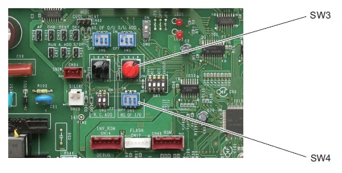
The number of indoor units set with the indoor unit quantity setting SW (SW3, SW4) on the circuit board of the outdoor unit is too high
The control lines between the indoor units have been disconnected.
Location:
Refer to the maintenance material for the test run and check the quantity setting of the indoor unit SW (SW3, SW4).
Check the control lines between the units on the indoor and outdoor units
Correction:
Perform the automatic address setting again after correcting the quantity setting of the indoor unit or the wiring between the units
Notes:
3WAY switch position
E16: Automatic address setting alarm (too many units)
Alarm conditions:
The number of indoor units was too small when the automatic address setting was carried out
After the initial communication, an unrecognised unit was recognised
Possible cause:
The number of indoor units set in the indoor unit volume setting SW (SW3, SW4) on the outdoor unit board is less than the set number
The control lines between the units are incorrectly wired
Location
Refer to the maintenance material for the test run and check the quantity setting of the indoor units
Check the control lines between the units on the indoor and outdoor units
Correction:
Perform the automatic address setting again after correcting the quantity setting of the indoor unit or the wiring between the units
Error code E20: No indoor unit during automatic address setting
Alarm conditions
No indoor units were recognised in the automatic address setting
Possible cause:
The control lines between the indoor units have been disconnected
Serial connector 1 (CN76) is not connected to the outdoor unit
The power supply is switched off on all indoor units in the system
Location:
Check whether the control lines between the units from the outdoor unit to the indoor units are interrupted
Check whether the serial connector 1 (CN76) on the outdoor unit is removed
Check the power supply to the indoor units
Correction:
Reconnect the control cable between the units from the outdoor unit to the indoor unit
Notes:
Position of the CN76 serial connector on 3-pin


Error code E24: Outdoor unit could not receive communication from another outdoor unit
Alarm conditions:
After the initial communication was completed, communication from an outdoor unit was interrupted
Possible cause:
After the first communication was completed, the control wiring between the main and secondary outdoor units was interrupted
The power supply to the outdoor unit was turned off after the first communication
Error code E25: Outdoor unit address setting error (duplicated)
Alarm conditions:
Within 3 minutes, communication was received five times or more on the main sub-control wiring of the outdoor unit with the same address as this unit
Possible cause:
The unit number is set incorrectly
Location:
Recheck the unit numbers
Notes:
Recovery from this alarm is automatic (if there is no communication with the same address for 3 minutes).
Error code E26: Incorrect number of outdoor units
Alarm conditions:
After power initialisation, the set outdoor unit quantity for 3 minutes or longer did not match the number of outdoor units recognised on the control line between the outdoor units
Possible cause:
The outdoor unit quantity is set incorrectly
The outdoor unit control cable is disconnected
Location:
Recheck the outdoor unit settings
Check the outdoor unit control lines
Correction:
Correct the incorrect outdoor unit quantity settings
Repair the outdoor unit control cable.
Notes:
The restoration after this alarm is automatic (if the set number of outdoor units matches the number of outdoor units recognised on the control line of the outdoor units).
E 29: Outdoor unit error when receiving the relay control unit
Alarm conditions:
The communication between the outdoor unit and the outdoor unit (main unit) has been interrupted for at least 3 minutes
Possible cause:
After the first communication processes were completed, the control line between the outdoor units was interrupted
After the first communication was completed, the RC connector was removed
The power supply on the outdoor unit (main unit) is turned off
Location:
Check the outdoor unit control lines
Check the RC connections
Check the power supply on the outdoor unit (main unit)
Correction
Repair the outdoor unit control cable.
Correct the RC connection
Turn on the outdoor unit (main unit)
Error code E30: Error when transmitting to the outdoor units
Possible causes:
During the automatic address setting, the number of connected devices does not correspond to the set number.
If you switch on the power supply, the number of connected devices does not correspond to the set number.
Outdoor unit serial transmission error
Error code E31: Wiring error between the circuit boards
Possible cause: When does it happen?
- An error occurred while rewriting the microcomputer
- If the device is switched off while rewriting the microcomputer
- Without wiring between the board and the ROM burner
Location:
Rewrite the micro-computer
Turn the unit on again
Correction:
Replace control board
Error code F04: Error in the compressor 1 outlet temperature
Alarm conditions:
Discharge temp. of 100°C or higher was found 30 minutes or more after the compressor stopped
Discharge temp. of 80°C or higher was found after all compressors were stopped for 60 minutes or longer
A / D step is 10 steps or less (short circuit)
Possible cause:
1. Malfunction of the sensor
- Malfunction of the sensor element
- The sensor wiring is partially disconnected, which leads to increased electrical resistance
- This alarm does not occur if the wiring is interrupted or the plug is not connected to the circuit board of the outdoor unit
2. Wiring crossed or installation failure
- The outlet temperature sensor of this compressor is connected to the outlet pipe of the other compressor
- The connector for the outlet temperature sensor of the problem compressor is connected to the PCB connector of the outdoor unit for the other compressor
3. Circuit board fault in the outdoor unit
4. The check valve on the outlet pipe for this compressor is wet
5. An air short circuit blockage in the area of the outdoor unit raised the ambient temperature of the outdoor unit and reduced the cooling effects after the compressor stopped
6. There is a cause that leads to a P03, P17 or P02 alarm
7. Electrical noise
Location:
1. Malfunction of the sensor and failure of the outdoor unit circuit board
- Constantly shows a high temperature
- If monitoring software or other means of monitoring are used, the discharge temperature can fluctuate suddenly and wildly in some cases
- In some cases the exact temperature may not be known, even if surveillance software is used
Error code F04: Error in the compressor 2 outlet temperature
Alarm conditions:
Discharge temp. of 100°C or higher was found 30 minutes or more after the compressor stopped
Discharge temp. of 80°C or higher was found after all compressors were stopped for 60 minutes or longer
A / D step is 10 steps or less (short circuit)
Possible cause:
1. Malfunction of the sensor
- Malfunction of the sensor element
- The sensor wiring is partially disconnected, which leads to increased electrical resistance
- This alarm does not occur if the wiring is interrupted or the plug is not connected to the circuit board of the outdoor unit
2. Wiring crossed or installation failure
- The outlet temperature sensor of this compressor is connected to the outlet pipe of the other compressor
- The connector for the outlet temperature sensor of the problem compressor is connected to the PCB connector of the outdoor unit for the other compressor
3. Circuit board fault in the outdoor unit
4. The check valve on the outlet pipe for this compressor is wet
5. An air short circuit blockage in the area of the outdoor unit raised the ambient temperature of the outdoor unit and reduced the cooling effects after the compressor stopped
6. There is a cause that leads to a P03, P17 or P02 alarm
7. Electrical noise
Location:
1. Malfunction of the sensor and failure of the outdoor unit circuit board
- Constantly shows a high temperature
- If monitoring software or other means of monitoring are used, the discharge temperature can fluctuate suddenly and wildly in some cases
- In some cases the exact temperature may not be known, even if surveillance software is used
Error code F06: Outdoor unit heat exchanger 1 gas (inlet) temperature sensor faulty
Alarm conditions:
- A / D step is 10 steps or less (short circuit)
- A / D step is 1014 steps or more (open circuit)
Possible cause:
- Default of the sensor (including connector)
- PCB fault
Location:
- Measure the sensor resistance. Check whether the sensor is functioning normally
- Use a remote control or PC monitor to check the temperature detected by the microcomputer.
Error code F07: Outdoor unit heat exchanger 1 liquid temperature sensor (outlet) faulty
Alarm conditions:
A / D step is 10 steps or less (short circuit)
A / D step is 1014 steps or more (open circuit)
Possible cause:
Sensor malfunction (including connector)
Circuit board fault
Location:
Measure sensor resistance. Check whether the sensor is functioning normally
Use a remote control or PC monitor to check the temperature detected by the microcomputer
Error code F08: Outside temperature sensor faulty
Alarm conditions:
A / D step is 10 steps or less (short circuit)
A / D step is 1014 steps or more (open circuit)
Possible cause:
Sensor malfunction (including connector)
PCB fault
Location:
Measure sensor resistance. Check whether the sensor is functioning normally
Use a remote control or PC monitor to check the temperature detected by the microcomputer
Error code F12: Compressor inlet temperature sensor faulty
Alarm conditions:
A / D step is 10 steps or less (short circuit)
A / D step is 1014 steps or more (open circuit)
Possible cause:
Sensor malfunction (including connector)
PCB fault
Location:
Measure sensor resistance. Check whether the sensor is functioning normally
Use a remote control or PC monitor to check the temperature detected by the microcomputer
Error code F14: Overcooling gas temperature sensor faulty
Alarm conditions:
A / D step is 10 steps or less (short circuit)
A / D step is 1014 steps or more (open circuit)
Possible cause:
Sensor malfunction (including connector)
PCB fault
Location:
Measure sensor resistance. Check whether the sensor is functioning normally
Use a remote control or PC monitor to check the temperature detected by the microcomputer
Error code F16: High pressure sensor faulty, high load
Alarm conditions:
High pressure sensor not connected or open circuit
The high pressure sensor continuously measured over 3.6 MPa for 30 minutes while the outdoor units stopped
High pressure sensor detected over 3.6 MPa while outdoor units were operating
(In some cases, start and stop may be repeated due to the pre-trigger mode.)
Possible cause
Defective high pressure sensor
Error connecting the connector to the outdoor unit circuit board
Error when the service valve in the outdoor unit opened
Blocked refrigerant circuit
Refrigerant overfilled
Circuit board fault in the outdoor unit
Location:
1. High pressure sensor failure
Check the sensor resistance value. (use a tester and measure the resistance between sensor No1 and No3)
- A resistance of less than 95 kΩ indicates a short circuit or other problems
- A resistance of 95 kΩ - 105 kΩ (low pressure sensor pin 1-3) is normal
- A resistance of more than 105 kΩ indicates an interruption or other fault
Connect a pressure gauge to the low pressure outlet and check whether the value displayed by the monitoring software has changed and whether the pressure gauge pressure deviates significantly
During heating, check whether the temperature is below the highest temperature of the indoor unit E1
The pressure detected by the high pressure sensor is the highest pressure in the system. Therefore, the converted saturation temperature during heating will never be lower than the indoor unit’s E1 temperature. During cooling, this temperature is never lower than the outdoor unit fluid temperature
2. Error connecting the connector to the outdoor unit circuit board
Check the connector connected to the outdoor unit circuit board
3. The service valve cannot be opened
Check the open/closes condition of the valve
4. Check the refrigerant circuit for blockages
5. Check if the refrigerant is overfilled
In the event of blockage or overloading, refrigerant can accumulate in the outdoor unit (cooling) and in the indoor unit (heating). Sometimes there may be a sudden increase in pressure at start-up
6. Circuit board fault in the outdoor unit
The control points are the same as in the case of a malfunction of the high pressure sensor.
A normal PCB is needed to determine if the problem is a PCB fault or malfunction of the pressure sensor. If an abnormality of the high pressure sensor malfunctions is found in the test objects, first try to replace the circuit board and test again
The problem has been rectified: Outdoor unit circuit board error
The fault is not eliminated: High pressure sensor fault
Correction
1. Replace the high pressure sensor
When you replace a high pressure sensor, perform the refrigerant recovery of the outdoor unit
2. Replace circuit board
3. Rectify the refrigerant circuit fault
Open the outdoor unit valve
Clear blockage
If the refrigerant is overfilled, collect the appropriate amount of refrigerant
∗ Overloading standards. Install and check the manometer on the high pressure distance connector of the outdoor units
during cooling: Not available when the outdoor temperature is low or the outdoor fan is set. While both compressors 1 and 2 work in the blower mode with 12 or 13 steps, the saturation temperature of the high pressure indicates the outside temperature
+ around 15°C. If the temperature is 5°C above the specified temperature, an overload can be expected
During heating: In an indoor unit, the refrigerant flow is poor (E1 temperature and outlet temperature are low), and the mechanical valve of this device is open for at least 300 pulses and the E1 temperature is close to room temperature. However, note that this type of data often occurs when there is a height difference between indoor units. Reducing the amount of refrigerant improves the flow of refrigerant, but reducing it too much increases the likelihood of alarms related to low oil level (roller side), low pressure SW and outlet temperature. Act with caution
Notes:
Example: A malfunction had occurred when the fluid, suction and pressure pipes were blocked
Error code F17: Low pressure sensor faulty
Alarm conditions:
Sensor short circuit
Open sensor circuit
Possible cause:
Sensor malfunction (including connector)
PCB fault
Location:
Measure sensor resistance. Check whether the sensor is functioning normally
Use a remote control or PC monitor to check the temperature detected by the microcomputer
Error code F23: Outdoor unit heat exchanger 2 gas (inlet) temperature sensor faulty
Alarm conditions:
- A / D step is 10 steps or less (short circuit)
- A / D step is 1014 steps or more (open circuit)
Possible cause:
- Sensor malfunction (including connector)
- PCB fault
Location:
- Measure sensor resistance. Check whether the sensor is functioning normally
- Use a remote control or PC monitor to check the temperature detected by the microcomputer.
Error code F24: Outdoor unit heat exchanger 2 liquid temperature sensor (outlet) faulty
Alarm conditions:
A / D step is 10 steps or less (short circuit)
A / D step is 1014 steps or more (open circuit)
Possible cause:
Sensor malfunction (including connector)
Circuit board fault
Location:
Measure sensor resistance. Check whether the sensor is functioning normally
Use a remote control or PC monitor to check the temperature detected by the microcomputer
Error code F31: Error in the outdoor unit solid-state memory (EEPROM)
Alarm conditions:
There is no solid-state memory available for power initialisation
The read values do not match after writing to the solid-state memory is complete
Possible cause:
Memory was not inserted after the circuit board was replaced
The service life of the solid-state memory has been reached
The solid-state memory is installed incorrectly (wrong direction, bent pin, etc)
Location:
Check the solid-state memory on the circuit board
Error code H01: Compressor 1 current values not in the control range (overcurrent)
Alarm conditions:
The primary current of compressor 1 (INV) has detected an overcurrent that is higher than the values listed in the following table (overcurrent)
| Unit performance | 8 HP | 10 HP | 12 HP | 14 HP |
| Actual (A) | 15.1 | 19.8 | 21.0 | 21.0 |
Possible cause:
Wiring error
Operation under extremely high pressure (overloaded operation)
Power source and voltage failure (sudden voltage drop)
Location:
1. Wiring error
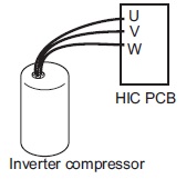
Check whether the connection between "HIC PCB" and "Inverter Compressor" is faulty. See Figure
2. Operation under extremely high pressure (overloaded operation)
Error opening the service valve of the outdoor unit. Check the open/closed condition of the outdoor unit’s maintenance valve
High pressure sensor performance map difference (under-shift)
Connect a pressure gauge to the high pressure outlet and check whether the value displayed by the monitoring software has changed and whether the pressure gauge pressure deviates significantly
3. Check the power supply and the voltage
Correction:
1. Wiring error
Loosen the wiring and rectify wiring error
2. Operation under extremely high pressure (overloaded operation)
Open the outdoor unit service valve
Replace high pressure sensor
When you replace a high pressure sensor, perform the refrigerant recovery of the outdoor unit
3. Improvement of the current source and the voltage
Error code H03: CT sensor for compressor 1 not connected, short circuit
Alarm conditions:
Compressor 1: When compressor 1 (INV) is stopped, the primary current is sensed above 18A. * If the frequency of compressor 1 (INV) is above 35 Hz and the secondary current is above 7.0 A, a primary current of less than 0.7 A is detected
* No current is recognised even though the compressors are operating
Possible cause:
Transformer circuit failure (including cable break etc.)
Transformer circuit plug removed
Phase missing to which the current transformer circuit is connected
This transformer circuit is connected to the connection of the other transformer circuit
PCB error
Electrical noise
Location:
1. CT circuit failure, PCB failure
Problem: The current value during compressor operation is below the threshold.
Test:
Make sure that the plug is not removed
Check the continuity of the transformer circuit.
Install a normal transformer instead of this transformer and check it. If current is detected, the circuit board can be judged to be OK -> transformer fault
• Check whether current flows in the phase to which the current transformer circuit is connected -> Check the voltage and the current
2. Crossed wiring or installation error
Problem: If the compressor is stopped, the actual value on the other compressor is high. ☆ If this type of condition occurs, the recording of the occupancy has priority.
3. If after checking the above items the cause is still unknown, it is possible that the noise is the cause of the problem. It is necessary to connect a PC or other instrument.
Correction:
Replace the transformer circuit
Replace the outdoor unit circuit board.
Rectify the problem
Notes:
Example: The connector was not inserted after the circuit board was replaced.
Use a normal current transformer as an aid to determine whether the problem is a circuit board fault or a transformer fault.
Error code H05: Compressor 1 outlet temperature sensor not connected
Alarm conditions:
This alarm occurs when the temperature sensor of the discharge sensor is not inserted in the sensor holder of the tube or when the sensor itself malfunctions other than as a cut wire
At an outside air temperature of -10°C or higher: An alarm is triggered if the temperature detected by the outlet sensor has changed by less than 2°C, if the compressor has been in operation for 10 minutes immediately after starting.
If the outside air temperature is lower than -10°C: An alarm is triggered if the temperature detected by the outlet sensor has changed by less than 2°C, if the compressor has been in operation for 30 minutes immediately after starting.
Possible cause:
The detector for the temperature of the discharge sensor is not inserted in the sensor holder of the tube
The discharge sensor itself has a different malfunction to a cut wire
Location:
Check whether the outlet temperature sensor is inserted in the sensor holder
Make sure that enough thermally conductive putty is applied.
Remove the discharge sensor from the sensor holder and expose the sensor to outside air for about 5 minutes. Make sure that the temperature detected by the sensor adapts to the outside air temperature. (However, the sensor cannot detect temperatures at or below 0°C.)
Correction:
Place the sensor in the holder and apply sufficient heat-conductive putty.
If the sensor is defective, replace it
Error code H06: Low pressure uncontrolled pressure drop
Alarm conditions:
The low pressure sensor continuously detects less than 0.06 MPa for 2 minutes or less than 0.02 MPa for a moment
Possible cause:
Defective low pressure sensor
Error when the service valve in the outdoor unit opened
Blocked refrigerant circuit
Lack of refrigerant gas
Refrigerant accumulates in the stopped outdoor units
Location:
1. Low pressure sensor defective
Check the sensor resistance value (use a tester and measure the resistance between sensor No1 and No3)
- A resistance of less than 95 kΩ indicates a short circuit or other problems
- A resistance of 95 kΩ - 105 kΩ (low pressure sensor pin 1-3) is normal
- A resistance of more than 105 kΩ indicates an interruption or other fault
Connect a pressure gauge to the low pressure outlet and check whether the value displayed by the monitoring software has changed and whether the pressure gauge pressure deviates significantly
2. The outdoor unit service valve can not be opened
Check the open/closed condition of the maintenance valve
3. Check the refrigerant circuit for blockages
If the refrigerant circuit is blocked, the refrigerant will not return to the compressor. As a result, the vacuum may occasionally decrease abnormally. Then check the following points: Solenoid valve, expansion valve, stains caused by dirty water in the circuit, etc
4. Lack of refrigerant gas
If there is a lack of refrigerant charge or amount in the system caused by gas leakage, the low pressure may occasionally decrease abnormally
5. Refrigerant is accumulated in the stop mode of the outdoor units
Leakage of expansion valve and solenoid valve in the outdoor unit in stop mode, etc
Correction:
1. Replace the low pressure sensor
If you replace a low pressure sensor, perform the refrigerant recovery on the outdoor unit
2. Rectify the refrigerant circuit fault
Open the outdoor unit valve
Clear blockage
Resolve insufficient refrigerant gas (correction of gas leakage, additional refrigerant, etc.)
If you top up due to lack of refrigerant, gradually add 500 g of refrigerant each time
Notes:
Example:
The alarm had occurred due to a lack of refrigerant due to a gas leak
The alarm occurred when the fluid, suction and pressure pipes were blocked
Error code H08: Fault (open circuit) on the oil sensor (connection) on the compressor 1
Alarm conditions:
This alarm occurs when a connection (pins 1 and 2 for compressor 1, pin 4 and 5 for compressor 2) is open.
Possible cause:
Plug removed
Location:
Check whether the connector is firmly connected
Correction:
Connect the plug
Correct the connection on pins 4 and 5
Error code H11: Compressor 2 current values incorrect (overcurrent)
Alarm conditions:
During operation, the compressor current exceeded 12 A for at least 30 seconds. However, this alarm is not recognised 4 seconds after the compressor startsPossible cause:
- Compressor failure (blocked or partially blocked)
- Transformer fault (including cable break)
- Missing power phase
- Low voltage
- PCB error
Location:
1. Compressor failure (partially locked)
Problem: The actual value during operation considerably exceeds the value given above.
Test: If the current for each phase is measured with a clamp meter or similar instrument, check that the current value for all phases is not high. If MG has been switched on (caution), make sure that no compressor noises occur or that the compressor does not run with a groaning noise.
2. CT circuit failure, PCB failure
- Check for bad connector contact
- Check continuity of the transformer circuit
- Install a normal transformer instead of this transformer and check it. If current is detected, the board can be repaired → CT circuit failure
- Check whether current flows in the phase to which the transformer circuit is connected -> Check the voltage and the current
3. Missing power phase
Problem: This alarm mainly occurs when the T phase is missing. If the R phase or S phase is missing, transformer or PCB continuity problems arise. However, this may not apply in the event of a missing phase caused by a magnetic SW error.
Check: There is a possibility of a magnetic SW error. Therefore, check the phase voltage in a location as close as possible to the compressor.
4. Low voltage
Problem: In most cases, this occurs when another constant speed compressor (including compressors in other units) or another unit is started. This also occurs when the power cables are extremely long.
Test: Check the voltage between the individual phases. However, if this occurs when starting other units or compressors, an oscilloscope is required.
5. PCB error
Test: Make sure that the current value measured with the clamp meter is not below the value measured with the PC or the remote control
6. If after checking the above items the cause is still unknown, it is possible that noise is the cause of the problem. It is necessary to connect a PC or other instrument
Correction:
- Replace the compressor
- Replace the transformer circuit
- Repair the circuit
- Adjust the primary side power. Repair the power cables
- Replace the outdoor unit circuit board
- Rectify the fault
In the event of a compressor failure, measures may need to be taken to remedy the cause of the compressor failure (e.g., fluid blockage) to prevent a new occurrence. Make sure that there is no cause for the compressor blocking
Error code H13: CT sensor for compressor 2 not connected, short circuit
Error code H03: CT sensor for compressor 1 not connected, short circuit
Alarm conditions:
Compressor 2: The current value on compressor 2 is less than 2.0 A after 2 seconds or more have passed after the compressors started operating and performing.
Possible cause:
Transformer circuit failure (including cable break etc.)
Transformer circuit plug removed
Phase missing to which the current transformer circuit is connected
This transformer circuit is connected to the connection of the other transformer circuit
PCB error
Electrical noise
Location:
1. CT circuit failure, PCB failure
Problem: The current value during compressor operation is below the threshold.
Check:
- Make sure that the plug is not disconnected
- Check the continuity of the current transformer circuit
- Install a normal current transformer instead of this current transformer and check it. If current is detected, the circuit board can be assessed as OK -> transformer fault
- Check whether current flows in the phase to which the transformer circuit is connected -> Check the voltage and the current
2. Crossed wiring or installation error
Problem: If the compressor is stopped, the actual value on the other compressor is high. ☆ If this type of condition occurs, the recording of the occupancy has priority.
3. If after checking the above items the cause is still unknown, it is possible that the noise is the cause of the problem. It is necessary to connect a PC or other instrument.
Correction:
- Replace the transformer circuit
- Replace the outdoor unit circuit board
- Rectify the problem
Notes:
example: The connector was not inserted after the circuit board was replaced.
Use a normal current transformer as an aid to determine whether the problem is a circuit board fault or a transformer fault.
Error code H15: Compressor 2 outlet temperature sensor not connected
Alarm conditions:
This alarm occurs when the temperature sensor of the discharge sensor is not inserted in the sensor holder of the tube or when the sensor itself malfunctions other than as a cut wire
At an outside air temperature of -10°C or higher: An alarm is triggered if the temperature detected by the outlet sensor has changed by less than 2°C, if the compressor has been in operation for 10 minutes immediately after starting.
If the outside air temperature is lower than -10°C: An alarm is triggered if the temperature detected by the outlet sensor has changed by less than 2°C, if the compressor has been in operation for 30 minutes immediately after starting.
Possible cause:
The detector for the temperature of the discharge sensor is not inserted in the sensor holder of the tube
The discharge sensor itself has a different malfunction to a cut wire
Location:
Check whether the outlet temperature sensor is inserted in the sensor holder
Make sure that enough thermally conductive putty is applied.
Remove the discharge sensor from the sensor holder and expose the sensor to outside air for about 5 minutes. Make sure that the temperature detected by the sensor adapts to the outside air temperature. (However, the sensor cannot detect temperatures at or below 0°C.)
Correction:
Place the sensor in the holder and apply sufficient heat-conductive putty.
If the sensor is defective, replace it
Error code H21: Compressor 2 HIC Alarm
Alarm conditions
During operation, the compressor current exceeded 14 A for at least 4 seconds. However, this alarm is not recognised 2 seconds after the compressor starts
Possible cause:
- Compressor failure (blocked or partially blocked)
- Transformer fault (including cable break)
- Missing power phase
- Low voltage
- PCB error
Location:
1. Compressor failure (partially locked)
Problem: The actual value during operation considerably exceeds the value given above.
Test: If the current for each phase is measured with a clamp meter or similar instrument, check that the current value for all phases is not high. If MG has been switched on (caution), make sure that no compressor noises occur or that the compressor does not run with a groaning noise.
2. CT circuit failure, PCB failure
- Check for bad connector contact
- Check continuity of the transformer circuit
- Install a normal transformer instead of this transformer and check it. If current is detected, the board can be repaired → CT circuit failure
- Check whether current flows in the phase to which the transformer circuit is connected -> Check the voltage and the current
3. Missing power phase
Problem: This alarm mainly occurs when the T phase is missing. If the R phase or S phase is missing, transformer or PCB continuity problems arise. However, this may not apply in the event of a missing phase caused by a magnetic SW error.
Check: There is a possibility of a magnetic SW error. Therefore, check the phase voltage in a location as close as possible to the compressor.
4. Low voltage
Problem: In most cases, this occurs when another constant speed compressor (including compressors in other units) or another unit is started. This also occurs when the power cables are extremely long.
Test: Check the voltage between the individual phases. However, if this occurs when starting other units or compressors, an oscilloscope is required.
5. PCB error
Test: Make sure that the current value measured with the clamp meter is not below the value measured with the PC or the remote control
6. If after checking the above items the cause is still unknown, it is possible that noise is the cause of the problem. It is necessary to connect a PC or other instrument
Correction:
- Replace the compressor
- Replace the transformer circuit
- Repair the circuit
- Adjust the primary side power. Repair the power cables
- Replace the outdoor unit board
- Rectify the fault
In the event of a compressor failure, measures may need to be taken to remedy the cause of the compressor failure (e.g., fluid blockage) to prevent a new occurrence. Make sure that there is no cause for the compressor blocking
Error code H27: Compressor 2 Oil detection sensor (connection) defective
Alarm conditions:
This alarm occurs when a connection (pins 4 and 5 for compressor 2) is open.
Possible cause:
Plug removed
Location:
Check whether the connector is firmly connected
Correction:
Connect the plug
Correct the connection on pins 4 and 5
Error code H31: Compressor 1 HIC Alarm
Alarm conditions:
This alarm occurs when the microcomputer detects an error signal (indicating an abnormal HIC temperature or other problems) from the HIC.
The HIC assesses the current and the temperature and outputs the error signal. In general, this indicates problems with the HIC itself.
Possible causes:
Overcurrent in the HIC circuit and the resulting abnormal warming caused by a HIC error
Location:
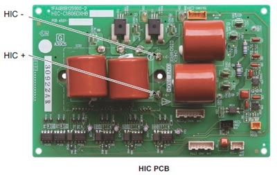
Check the power and connector wiring. If the wiring and connections are normal, use a tester to measure the resistance between the HIC performance of the compressor (HIC +) and ground (HIC–). In the event of a short circuit, there is a HIC malfunction.
Check the figure below
Correction:
If a HIC error is found, replace the board
Notes:
Switch off the power supply and check the continuity of HIC + and HIC– on the HIC board
Error code L04: The address settings of the outdoor unit have been duplicated
Alarm conditions:
Within 3 minutes, communication was received five times or more via the control wiring between the units containing the same address as this unit
Possible cause:
Incorrect outdoor system address settings
Location:
Recheck the system address settings
Correction:
Correct the system address settings
Notes:
Restoration after this alarm is automatic (if the communication containing the same address as this device is not received 3 minutes after detection).
Error code L05: Priority of indoor unit duplicated (For indoor priority)
Alarm conditions:
Remote control without priority setting
Possible causes:
There are 2 or more indoor unit controls that take precedence over the operating mode in the refrigerant circuit.
Error code L05: Indoor unit double prioritised (not for prioritised indoor) and outdoor unit
Alarm conditions:
Remote control with priority set
Possible causes:
There are 2 or more indoor unit controls that take precedence over the operating mode in the refrigerant circuit.
Error code L10: The capacity of the outdoor unit was not set
Alarm conditions:
The capacity of the outdoor unit has not been set or the setting is not allowed by the system
Location:
Connect the remote control for maintenance of the outdoor unit. On the outdoor unit detailed EEPROM setting mode screen, check the outdoor unit capacity value (item code 81). Make sure it is not set to "0" or a capacity that is not allowed.
Correction:
If article code 81 is incorrect, use the remote control to maintain the outdoor unit and set it properly.
After changing the setting, make sure that you reset both the indoor and outdoor voltage
Notes:
The remote controller for maintenance of the outdoor unit is required to set the refrigerant type in the EEPROM of the outdoor unit.
Error code L17: Outdoor unit model not matching
Alarm conditions:
This alarm occurs when a unit other than a R410A refrigerant unit is connected
Possible cause :
A refrigerant unit R407C or a model R22 unit was accidentally connected
The connected unit is correct, but the refrigerant type setting in the outdoor unit's EEPROM (item code 80) is incorrect.

Location:

Check the type of refrigerant on the connected unit
Use the remote control to maintain the outdoor unit and check the refrigerant with article number 80. If the setting is incorrect, change it in R410A

Notes:
The remote control for maintenance of the outdoor unit is required to set the refrigerant type in the EEPROM of the outdoor unit.
Error code L18: 4-way valve spool separated, line separated
Alarm conditions:
During heating mode (comp. ON), the highest detected temperature on a heat exchanger of the outdoor unit (EXG 1, EXG 2, EXL 1 or EXL 2) was 20°C or more above the outside air temperature (air temp.) continuously for 5 minutes or longer or the recorded intake temperature (SCT) was 20°C or more above the outside air temperature continuously for 5 minutes or longer.
Possible causes:
The 4-way valve connector (20S CN022) was disconnected from the control board
The 4-way valve circuit is blocked (fault)
Location:
Check the 4-way valve connector (20S CN022)
If the connector is normal, check the 4-way valve wiring and the PCB circuit
Correction:
If the connector is normal, correct or replace the problem areas
Error code P03: Error in the compressor 1 outlet temperature
Alarm conditions:
The temperature is 106°C or more and there was a stop before triggering.
The alarm occurs when the stop occurs more than once before triggering. However, the flow counter is cleared if the compressor runs continuously for a certain period of time.
Possible causes
- Blockage of the liquid valve capillaries
- Insufficient amount of refrigerant (including problems due to insufficient initial charge and gas leakage)
- Blocking of low-pressure parts through the penetration of foreign bodies (moisture, scale, etc.)
- Crossing (hose or circuit board connector) with the other compressor thermistor
- Malfunction of the expansion valve
- Accumulation of refrigerant on stopped outdoor units
- Sensor for compressor discharge defective
- PCB- Error (A / D conversion error)
- Electrical noise
Location:
1. Capillary blockage
Problem: The compressor outlet temperature does not drop even if the fluid valve is switched on.
Control: If the fluid valve is in operation and the fluid valve is switched on, check whether the secondary side of the fluid capillaries is cold.
2. Too little refrigerant
Problem: The fluid effect is bad
Test: Check whether or not the superheat temperature drops when the mechanical valve of the evaporator is opened to 300 pulses or more (after checking for foreign matter).
3. Contamination by foreign bodies
Problem: The effectiveness of the fluid valve is poor
Control: Make sure that there is no difference in condensation or frost conditions between the primary and secondary tubes of the strainer.
4. Crossed thermistor
Problem: The outlet temperature of the other compressor is high, although only this compressor is in operation
When the fluid valve turns on, the outlet temperature of the other compressor drops.
5. Accumulation of refrigerant in stopped outdoor units
Problem:
- The system is OK when all outdoor units are in operation. However, when a specific outdoor unit is stopped, symptoms of insufficient gas supply appear
- Condensation or frost is visible up to the top of the accumulator of the stopped outdoor unit
- After stopping an outdoor unit, the sound that refrigerant flows into an outdoor unit that lasts for a long time is heard
- If an outdoor unit starts after a long period, the startup is accompanied by strong vibrations
Check:
Representative parts are the liquid capillaries (the secondary side of the capillaries is cool during cooling operation), the mechanical valve, the mechanical valve bypass check valve (refrigerant flow noise can be heard and stops when the liquid valve is closed) and the hot gas defrost valve (if the secondary valve side is still hot after a long period of time, be careful not to confuse the transferred heat with a valve failure.)
Ice grows on the lower parts of some heat exchangers for outdoor units, but not on others. Because this problem can also occur with outdoor units with a high operating speed under conditions with insufficient gas, caution should be exercised.
6. Sensor defective
Test:
- This alarm is likely to occur when the wiring is partially broken. (It is difficult to identify even if the continuity is checked.) The detected discharge temperature is high
- Although such conditions rarely occur, a P02 alarm is likely when the detected discharge temperature is low
- Replace the sensor with another discharge sensor and compare the temperature conditions
7. If the cause is not known after checking the above points, it is possible that the electrical noise is the cause of the fault.
Correction
- Replace the sensor.
- Replace the outdoor unit circuit board.
- Correct the problem areas.
Notes:
Example: All possible causes
Works continuously for a set period of time
Shows 2.5 minutes or more for an inverter unit and 30 seconds or more for a constant speed compressor
Error code P04: Operation of the high pressure switch
Alarm conditions:
The operation of the electronic circuit in the high pressure switch can short-circuit the connection depending on the pressure. The terminal is short-circuited at a pressure of 3.3 MPa or more. As soon as the connection is short-circuited, it remains in this state until the pressure drops below 2.6 MPa
Possible cause:
- Failure of the check valve in the pressure pipe of the compressor
- The service valve is closed
- Blockage of the outdoor heat exchanger when cooling down
- An air short in the outdoor unit while cooling down
- External fan failure during cooling
- Blockage of the air filter in the indoor unit while heating
- Air short circuit in the indoor unit during heating
- Internal fan failure when heating
- Refrigerant circuit blockage
- Mechanical valve failure
- Failure of the solenoid valve set
- Too much refrigerant has been charged
- High pressure switch failure
Location:
- Make sure that the high pressure switch connector is correctly connected
- When the high pressure switch is properly connected, connect a high pressure manometer to the high pressure outlet and monitor the pressure during operation to check the pressure when the high pressure switch is activated. The check valve is likely to fail if the pressure is less than 3.3 MPa. The following describes tests that must be carried out at high pressure
- While cooling down, check whether the heat exchanger of the outdoor unit is blocked. Remove any foreign objects that obstruct ventilation
- While cooling down, check whether an air short has occurred in the outdoor unit. The system works normally unless the temperature around the outdoor unit is too high.
- While cooling down, check whether the outdoor fan is defective. Check whether the screws securing the fan are loose and that the fan connector on the outdoor unit PCB is properly connected.
- While heating, check whether the air filters in the indoor unit are blocked. If it is blocked, clean the filter
- While heating, check whether there is an air short in the indoor unit. The system works normally unless the temperature around the outdoor unit is too high.
- While cooling down, check whether the outdoor fan is defective.
- Check if the refrigerant circuit is blocked. Check that all service valves are closed. Check whether the welds are blocked
- Check whether the mechanical valve is defective. Check if the mechanical valves cause rattling when resetting the power supply. Since the mechanical valve in the indoor unit is in a place that makes it difficult to test by ear, use an electrical device for testing. Check that the mechanical valve connector pin on the board outputs 4V. Also check that the coil resistance of the mechanical valve is several tens Ω.
- Check if the solenoid valve set is defective. Removing a coil that is switched on results in a clicking sound. If you remove a coil that is turned off, no such noise will be generated
- Check whether the refrigerant has been overcharged. Too much refrigerant has been charged when the subcooling temperature of the condenser is 15°C or higher.
Correction
Replace damaged components and correct the amount of refrigerant charged
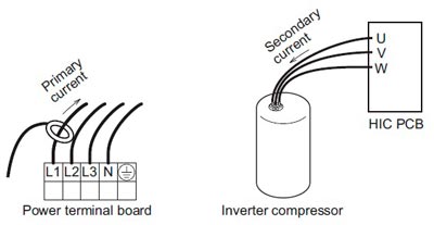
Error code P05: Open phase detection for compressor 1
Alarm conditions:
This alarm occurs when a phase reversal or a missing phase is detected in phases L1-L2-L3-N
Possible cause:
Reversed phase or missing phase in phases L1-L2-L3-N
Location:
Check the cabling on the power terminal plate
Correction:
Swap the phases and reinsert them. Check if the result is in order
Error code P11: Cooling water frozen (chiller)
Error code P14: Activation of the O2sensor
Alarm conditions:
An error is evaluated if the outdoor unit receives the "O2 Alarm Generated" signal from the indoor unit
If the EEPROM setting of the indoor unit (item code 0B) is set to 0001, the EXCT input short-circuited
Correction:
1. System configuration Is an O2 sensor being used?
If YES, see 3.
If NO, see 2.
2. Internal EEPROM setting
Is the EEPROM setting, item code 0B, on the internal control card set to 001?
If YES see 3. after the change.
If NO, see 4.
3. EXCT wiring
Is the EXCT socket (cable) short-circuited?
If YES, change the wiring.
If NO, see 4.
4. Internal control card
Is the alarm triggered when the EXCT connector (cable) is disconnected and the power supply is reset? If YES, see 4-c. If NO, see 4-b.
As there is no error, see what happens
Internal control card defective -> Replace circuit board
Error code P15: Compressor 2 open phase detection
Error code P16: Compressor 1 secondary overcurrent
Alarm conditions:
This alarm occurs when a current fault or current detection fault occurs (when a fault judgment current is detected in the primary or secondary current or when an instantaneous secondary current of 18 A * or higher is detected).
* Changed, to output errors from current regardless of the frequency of the inverter. There are also 6 HP and 10 HP compressors
1. If more than the overcurrent values in the primary and secondary current specified in the table have been determined.
6TE compressors:
Primary 18A
Secondary stage 18A
10HP compressors:
Primary 21A
Secondary 21A
2. If more than the current values specified in the table are immediately detected in the secondary current.
6 HP compressors: Secondary 28A
10 HP compressors: Secondary 36A
Possible causes
There is a strong possibility of a compressor failure.
An alarm for current detection problems occurs when it is determined that no current is flowing after the start (DCCT is damaged). In this case, the cause is a DCCT error.
Location:
Check the power and connector wiring.
Correction
It is possible to solve this problem by limiting the maximum frequency.
Error code P17: Error in the compressor 2 outlet temperature
Alarm conditions:
The temperature is 106°C or more and there was a stop before triggering.
The alarm occurs when the stop occurs more than once before triggering. However, the flow counter is cleared if the compressor runs continuously for a certain period of time.
Possible causes
- Blockage of the liquid valve capillaries
- Insufficient amount of refrigerant (including problems due to insufficient initial charge and gas leakage)
- Blocking of low-pressure parts through the penetration of foreign bodies (moisture, scale, etc.)
- Crossing (hose or circuit board connector) with the other compressor thermistor
- Malfunction of the expansion valve
- Accumulation of refrigerant on stopped outdoor units
- Sensor for compressor discharge defective
- PCB- Error (A / D conversion error)
- Electrical noise
Location:
1. Capillary blockage
Problem: The compressor outlet temperature does not drop even if the fluid valve is switched on.
Control: If the fluid valve is in operation and the fluid valve is switched on, check whether the secondary side of the fluid capillaries is cold.
2. Too little refrigerant
Problem: The fluid effect is bad
Test: Check whether or not the superheat temperature drops when the mechanical valve of the evaporator is opened to 300 pulses or more (after checking for foreign matter).
3. Contamination by foreign bodies
Problem: The effectiveness of the fluid valve is poor
Control: Make sure that there is no difference in condensation or frost conditions between the primary and secondary tubes of the strainer.
4. Crossed thermistor
Problem: The outlet temperature of the other compressor is high, although only this compressor is in operation
When the fluid valve turns on, the outlet temperature of the other compressor drops.
5. Accumulation of refrigerant in stopped outdoor units
Problem:
- The system is OK when all outdoor units are in operation. However, when a specific outdoor unit is stopped, symptoms of insufficient gas supply appear
- Condensation or frost is visible up to the top of the accumulator of the stopped outdoor unit
- After stopping an outdoor unit, the sound that refrigerant flows into an outdoor unit that lasts for a long time is heard
- If an outdoor unit starts after a long period, the startup is accompanied by strong vibrations
Check:
Representative parts are the liquid capillaries (the secondary side of the capillaries is cool during cooling operation), the mechanical valve, the mechanical valve bypass check valve (refrigerant flow noise can be heard and stops when the liquid valve is closed) and the hot gas defrost valve (if the secondary valve side is still hot after a long period of time, be careful not to confuse the transferred heat with a valve failure.)
Ice grows on the lower parts of some heat exchangers for outdoor units, but not on others. Because this problem can also occur with outdoor units with a high operating speed under conditions with insufficient gas, caution should be exercised.
6. Sensor defective
Test:
- This alarm is likely to occur when the wiring is partially broken. (It is difficult to identify even if the continuity is checked.) The detected discharge temperature is high
- Although such conditions rarely occur, a P02 alarm is likely when the detected discharge temperature is low
- Replace the sensor with another discharge sensor and compare the temperature conditions
7. If the cause is not known after checking the above points, it is possible that the electrical noise is the cause of the fault.
Correction
- Replace the sensor.
- Replace the outdoor unit circuit board.
- Correct the problem areas.
Notes:
Example: All possible causes
Works continuously for a set period of time
Shows 2.5 minutes or more for an inverter unit and 30 seconds or more for a constant speed compressor
Error code P19: Compressor 2 start error (compressor block, wiring phase open, DCCT error)
Error code P20: High load (valve forgot to open)
Alarm conditions:
The high pressure rise is not quick, but the alarm occurs if the power does not reach the expected time
Possible causes
- I forgot to open the valve
- Malfunction of the mechanical valve
- Idle speed away from the outside fan
Location:
Check the valve, the mechanical valve and the outside fan.
Error code P22: Problems with the ventilator motor
Alarm conditions:
Fan motor start error, fan motor Hall IC input error
Possible cause:
Possible causes include a Hall IC input circuit fault and a fan HIC fault
Location:
Check the fan motor wiring, Hall IC wiring, and connector connections.
If the wiring and connections are OK, check that the Hall IC input circuit capacitor is firmly soldered to the control board of the outdoor unit. Also use a tester and measure the resistance between fan HIC power (HIC +) and ground (HIC–).
In the event of a short circuit, there is a HIC fault
Correction:
If the fan does not start, the following corrections may be effective
- If there is a fan HIC error or a circuit error, replace the board
- If the fan motor is blocked, replace the fan motor.
Notes:
Switch off the power supply and check the continuity of "+" and "-" on the fan circuit board.
Error code P29: Compressor 1 start error (compressor block, wiring phase open, DCCT error)
Alarm conditions:
This alarm can occur at start-up and occurs if a missing phase or lock is detected and if a DCCT error occurs.
Possible causes:
Generally, this alarm occurs when the refrigerant pressure equalisation is uneven at startup or when the inverter compressor locks up, there is no phase in the inverter compressor wiring, or a DCCT error occurs. This can be seen as a startup problem that is not caused by HIC
Location:
Check the power and connector wiring.
Correction:
DCCT error (replace circuit board) or compressor error
Notes:
Use a tester to measure the voltage between the DCCT output on the back of the PCB and the earth. If the voltage is not within 2 - 3 V, the DCCT is malfunctioning.
Fehlercode H20: Fehlfunktion der Wasserpumpe
Alarmbedingungen:
Wenn dieser Alarm 5 Sekunden angezeigt wird.
Mögliche Ursache :
- Betriebsstopp aufgrund eines Kurzschlusses in der Motorwicklung der Wasserpumpe.
- Betriebsstopp aufgrund eines Drahtbruchs im Wasserpumpenmotor.
- Betriebsstopp aufgrund eines Bruchs der Wasserpumpenkabel.
- Betriebsstopp aufgrund einer Störung des Wasserpumpenmotors 1PM.
- Betriebsfehler aufgrund einer fehlerhaften Leiterplatte des Innengeräts.
Korrektur:
- Ersetzen Sie die Wasserpumpe
- Ersetzen Sie die Innengerätplatine
How do you recognise the alarm display of LEDs 1 and 2 on the outdoor unit control board
LED 1 shows the TYPE of the alarm:
2 flashes = Alarm P
3 flashes = Alarm H
4 flashes = Alarm E
5 flashes = Alarm F
6 flashes = alarm L
LED 2 shows the number of the alarm:
1 = 1
2 = 2
3 = 3
As an example: If the LED 1 flashes 2 times and the LED 2 17 times, the alarm indicates error P17
This is repeated continuously.
