We can help you
This can be found at the top right of the home page under: Request access
You are only one step away from your online account! Please observe the following note: You can only register for the online shop with a valid Schiessl customer number. In this case, click on "Request access" in the navigation bar on the right and select the tab "I am already a Schiessl customer". Request access using your customer number and company details.
We will promptly arrange for the activation of your individual prices and send you your login details. You may start usingonline shop in the meantime. So do not hesitate to acquaint yourself with our products. When you have found the product you are interested in, you will be able to request a quote straight away. Please also note that, as wholesalers, we can only provide access to the online shop to commercial customers associated with the industry.
Are you a new customer and do not yet have a customer number? In this case, please use "New customer application".
Feel free to contact us if you have any questions!
You can reach us by telephone at the following number:
+43 662 455 777-0
or in writing by email at:
office@schiessl.at
At the top of the gray menu bar you will find a globe symbol  and next to it the country in which you are currently located. To change the country, click the icon and select the appropriate country.
This is found under: My account > My data
The following fields can be modified here:
Password
You can set a new password here.
Personal data
Quickly and easily change your personal data such as name, telephone number or email address as well as your company data such as company name, department and position. You can also upload your company logo.
Data for quote mode
Here you can manage data relating to your company such as your website address, your terms and conditions as well as payment terms and bank information. You can also maintain your introductory and closing texts so that these are automatically filled in when creating an offer. Further information about creating offers for customers can be found under “Create offer for end customer”.
This is found under: My account => Manage your own employees
It's a shame you want to leave us.
To delete your customer account please contact us at the following number:
+43 662 455 777-0
or in writing by email at:
office@schiessl.at
Kindly let us know what we can do better.
If you would like to delete a user, you can do so via the user management"Manage your own employees". Search for the relevant user and the user will be removed by clicking on the recycle bin icon to the right. More information on this topic can be found under"Manage users".
To switch between the gross or net view, click on the eye icon  in the gray menu bar at the top left or go to the "My account" area and select "Activate quotation mode" or “Disable offer mode“.
This can be found at the top right of the home page under: Login
To log in, enter your email address and password.
This is found under: Login > Forgot password
Have you forgotten your password? No problem! Simply enter your registered email address. We will send you an email with a link to change your password. Please also check your spam folder if you have not received the email and contact our customer service otherwise.
You can reach us by telephone at the following number:
+43 662 455 777-0
or in writing by email at:
office@schiessl.at
To ensure that you can use our website at any time and anywhere, we have created a platform-independent system to guarantee availability on all end devices.
Only on older versions that go back over 5 years, the compatibility is limited. This can lead to unexpected problems.
This is found under: Company
Would you like to learn more about us? Explore our company page.
Have fun browsing!
At the top right next to the account settings you will find a bell symbol  . All news will be displayed in summary.
This is found under: My account > Shopping carts
You can add a product to the shopping cart directly in the product overview, as well as on every detail page of the product. By clicking on the "Add to shopping cart"button, the following window opens: "Please select amount and cart". You can add the product to an existing shopping cart, create a new shopping cart and manage your shopping carts by clicking on "My shopping carts".
This is found under: My account > Favourites
You will find a list of your wish lists here. You can search and filter according to wishlist. You can rename, duplicate or delete individual wish lists here.
If you are in a wish list, you can add or delete products manually. You can also download the DATANORM of the complete wish list here.
This is found under: My account > Shopping carts
A fully featured shopping cart
Your shopping cart does not just contain the products you add to it, you can also configure the following areas:
- Reference number
- Supplier
- Invoice address
- Delivery and pick-up options
All products in the shopping cart are listed further below. You can also see the order number, description, quantity, as well as the price, subtotal and total price. The DATANORM is also available for download.
It is now possible to orders directly, to send an enquiry, to create a customer quote or to transfer the shopping cart to an employee. More information on managing employees can be found in "Manage users".
This is found under: My account > Open quotes
To request a quote, select "Shopping carts" in the upper right area. A drop-down window appears with an overview of your shopping carts. You can also manage these in the "My account" section. Select the relevant project. Once you are in your project, you can click on the ““Send enquiry”button to request an offer. The request will be forwarded to the relevant sales representative, who will process your quote and get in touch with you as quickly as possible.
You will find an overview of your requests under the "Open quotes” tab. All expired quotes are greyed out - these can be restored if necessary. Quotes that are about to expire are displayed in yellow. Orders can be searched, filtered and sorted.
To mark your product as your favorite, click on the star icon on the right corner of the product overview or in the detailed view. Then the window "Select wish list" appears. There you can put the product in an already existing list, create a new wish list or manage them by clicking on “My wish lists” . Your lists can also be managed in the “My Account” area.
This is found under: My account > My orders
A differentiation is made between the following statuses:
- Order created
- Processing
- Goods partially delivered
- Goods completely delivered
- Invoiced
- Completed
The status is shown in the order overview as well as in the detailed view.
This is found under: My account > My orders
You will find an overview of your orders here. Here you can see the order date, order number, reference number, order value and order status for each order. You can search, filter and sort orders.
Clicking on the order number of an order will take you to the detailed view. This is where you will find a list of all the products that you have ordered and if required, you can re-order individual products or place the entire order again.
Once the order is placed, the delivery note, invoice and GAEB x97 are available for download here.
This is found under: My account > Manage your own employees
You will find a list of all your created users. There is a pencil icon to the right of each employee. Click this to edit an employee. Personal data, the password as well as the permissions can be changed.
The following permissions can be assigned:
- View prices
- Show net prices
- Show discounts
- Inventory
- Process orders view
- Submit / Review reports
- Download invoices
- Download delivery notes
This is found under: My account > Manage your own employees
Do you want several of your employees to have access to our online shop? Simply setup your employees as users yourself. You can even set which functions are visible for which employee. This practical setting allows you to configure your customer account for the different roles in your company. Click on "New user" to create a new employee and assign them the desired rights for the Schiessl Online Shop.
This is found under: My account > Manage your own employees
To delete a user, select the recycle bin icon to the right of the employee you wish to delete. Clicking on the recycle bin will delete the corresponding user.
You will find a number of filter options to the left of your search result for products in the online shop. The filters are adapted to the product range in order to make the selection easier for you. You can, for example, filter by manufacturer, availability, dimensions or properties.
Reset filter
Do you no longer wish to narrow down your search results? You can then deactivate all filters with the "Clear all" button.
You can easily reach your desired product area in the online shop via our product navigation.
To do so, click on "Products" in the main menu on the home page. A menu will now open with the 12 main categories and our offers. Each of the main categories contains further subcategories. Clicking on a product area will show you all matching items from the online shop.
You can then narrow down your search results with various filters (seeFilter functions).
Search suggestions
As you enter your search term, a number of search hits will be suggested to you. These are sorted by categories and provide you with a quick overview of content that matches your search query.
Search results
The search results are also divided into categories so that you can find what you are looking for more quickly. They are displayed in different tabs.
Choose from the headings:
- Products
- News
- Locations
- Further articles
If a tab is not displayed, there is no search result in the corresponding category.
This is found under: Service => Request catalogue
Registered professional customers can order our catalogues free of charge!
Simply fill out the order form to receive the printed version of a product catalogue and we will arrange for dispatch immediately. Please state which catalogue you require and the quantity. These will then be sent to the address registered with us. Please specify a different delivery address in the message if you have one.
Order our new free catalogue now. You will find the order form here.
Have fun browsing!
You can clearly see whether a product is in stock or has to be ordered first with the stock information in the detailed view of a product. The product overview features a colour system with symbols to inform you whether your desired quantity is available.
Warehouse information
The type of availability is stated for each product.
There are 3 different types of items:
- Items from the stocked range: Items in stock
You are shown how many units are available in which stores. - Order item: Delivery item
Delivery is made on request. - Item is not in stock: Item not available
A product is no longer available or is only available in a bundle with matching products.
You can search, filter and sort quotes. Click on the respective item number to obtain the corresponding inventory information. This means you always know immediately whether the product is in our stocked range, whether it has to be ordered first or whether it is no longer available.
This is found under: Company > Schiessl Logo
Our logo is available for download in various formats:
- eps
- jpeg
- png
You will find all information about the product in the detailed view. You will find the gross and net prices next to the product image. These are only visible when you are logged in. This is because the prices have been individually adjusted for you. The quantity and availability are also indicated.
The following sections can be found in the detailed view:
- Description
- Scope of delivery
- Accessories / replacement parts
- Performance data
- Downloads (safety data sheets, REACH, RoHS, WEEE...)
- Alternatives
- Technical data
- DATANORM downloads
- Customers also bought
- Recently viewed products
High pressure switch in outdoor unit (F12)
Preconditions for fault message:
A pressure of 45 bar or higher has been detected by the high pressure switch for an outdoor unit operating in heating or cooling mode.
Causes:
1. Dust deposits on the heat exchanger of the outdoor unit
2. Air side short circuit in outdoor unit
3. Faulty circulating pump
4. Insufficient water flow in the system
5. Improper seal in the system
6. Service valve closed
7. Expansion valve or filter blocked
8. Too much refrigerant in the system
9. Faulty high pressure sensor and switch on outdoor unit
10. Faulty circuit board on outdoor unit
Fault detection:
Occurs 4x within 20 minutes
Further information can be found in this PDF.
Compressor rotation fault (F14)
Preconditions for fault message:
The position detection circuit in the compressor has recorded an incorrect speed.
Causes:
1. Compressor not connected
2. Faulty outdoor unit circuit board (main board)
3. Faulty compressor
Fault detection:
Occurs 4x within 20 minutes Further information can be found in this PDF.
Further information can be found in this PDF.
DC fan motor on outdoor unit blocked (F15)
Preconditions for fault message:
The speed detected by the hall generator on the fan motor was not between 50 and 2550 min-1.
Causes:
1. Shut-off following a short circuit in the fan motor coil.
2. Shut-off due to a broken fan motor coil.
3. Shut-off due to a broken wire to the fan motor.
4. Shut-off due to faulty hall generators in fan motor.
5. Disruption due to faulty board in outdoor unit.
Fault detection:
Occurs 2x within 30 minutes.
Further information can be found in this PDF.
Excessive power draw (F16)
Preconditions for fault message:
The transformer (CT) has detected excessive power draw (27.9 A) by the outdoor unit board in cooling or heating mode.
Causes:
1. Too much refrigerant in the system
2. Faulty outdoor unit board (main board)
Fault detection:
Occurs 3x within 20 minutes.
Further information can be found in this PDF.
Compressor overheat protection (F20)
Preconditions for fault message:
The compressor temperature sensor has detected that the compressor casing is above 112 °C in cooling or heating mode.
Causes:
1. Faulty compressor temperature sensor
2. Service valve closed
3. Insufficient refrigerant (leak)
4. Expansion valve or filter blocked
5. Faulty outdoor unit circuit board (main board)
6. Faulty compressor
Fault detection:
Occurs 4x within 30 minutes
Further information can be found in this PDF.
Power transistor module overheat protection (F22)
Preconditions for fault message:
The temperature sensor for the transistor module of the outdoor unit has detected a temperature above 112 °C in cooling or heating mode.
Causes:
1. Faulty fan motor on the outdoor unit
2. Faulty outdoor unit board (main board)
Fault detection:
Occurs 3x within 30 minutes.
Further information can be found in this PDF.
Excess current output (F23)
Preconditions for fault message:
An output current above 40.1 A ±5.0 A (UD07 to 09CE) or 44.7 A ±5.0 A (UD12 to 16CE) in cooling or heating mode has been measured on the main board of the outdoor unit.
Causes:
1. Faulty outdoor unit circuit board (main board)
2. Faulty compressor
Fault detection:
The fault persists for at least 7 seconds.
Further information can be found in this PDF.
Problem in refrigeration circuit (F24)
Preconditions for fault message:
1. In cooling and heating modes, the compressor frequency is higher than the rated frequency.
2. In cooling and heating modes, the operating current is between 0.65 and 1.65 A.
3. In cooling and heating modes, the difference between the water inlet temperature and the fluid temperature of the indoor unit<5 K.
4. In cooling and heating modes, the difference between the water inlet temperature and the fluid temperature of the indoor unit<5 K.
Causes:
1. Faulty water inlet temperature sensor or fluid temperature sensor in the indoor unit
2. Service valve closed
3. Insufficient refrigerant (leak)
4. Expansion valve or filter blocked
5. Faulty outdoor unit circuit board (main board)
6. Poor compressor performance
Fault detection:
Occurs 2x within 20 minutes.
Further information can be found in this PDF.
Problem with switch valve (F25)
Preconditions for fault message:
1. In heating mode, the pipe temperature in the indoor unit is below 0 °C with thermostats active.
2. In cooling mode, the pipe temperature in the indoor unit is above 45 °C thermostats active.
Causes:
1. Sensor error
2. Faulty connection
3. Faulty outdoor unit circuit board (power board or main board)
4. Faulty switch valve
Fault detection:
Occurs 4x within 30 minutes.
Further information can be found in this PDF.
High pressure fault in outdoor unit (F27)
Preconditions for fault message:
The high pressure switch in the outdoor unit remains open when the compressor is shut off.
Causes:
1. Faulty connection
2. Faulty switch
3. Faulty board in outdoor unit (main board)
Fault detection:
The fault persists for at least 1 minute.
Further information can be found in this PDF.
Fault with water outlet temperature sensor 2 in indoor device (F30)
Preconditions for fault message:
When starting and during cooling or heating operation, the measured temperature values from the water outlet temperature sensor are checked for plausibility.
Causes:
1. Faulty connection
2. Sensor error
3. Faulty board in indoor unit (main board)
Fault detection:
Incorrect measurement value for at least 5 seconds.
Further information can be found in this PDF.
Fault with external temperature sensor (F36)
Preconditions for fault message:
When starting and during cooling or heating operation, the measured temperature valves from the external temperature sensor are checked for plausibility.
Causes:
1. Faulty connection
2. Sensor error
3. Faulty board in outdoor unit (main board)
Fault detection:
Incorrect measurement value for at least 5 seconds.
Further information can be found in this PDF.
Fault with water inlet temperature sensor in indoor unit (F37)
Preconditions for fault alert:
When starting and during cooling or heating operation, the measured temperature values from the water inlet temperature sensor are checked for plausibility.
Causes:
1. Faulty connection
2. Sensor error
3. Faulty board in indoor unit (main board)
Fault detection:
Incorrect measurement value for at least 5 seconds.
Further information can be found in this PDF.
Fault with hot gas temperature sensor in outdoor unit (F40)
Preconditions for fault message:
When starting and during cooling or heating operation, the measured temperature valves from the hot gas temperature sensor are checked for plausibility.
Causes:
1. Faulty connection
2. Sensor error
3. Faulty board in outdoor unit (main board)
Fault detection:
Incorrect measurement value for at least 5 seconds.
Further information can be found in this PDF.
Inverter controller fault (PFC, F41)
Preconditions for fault message:
In cooling and heating modes, the PFC breaker measures an unusually high DC voltage on the main board of the outdoor unit.
Causes:
1. Excess power supply voltage
2. Unequal resistances in the compressor coils
3. Faulty circuit board on outdoor unit
Fault detection:
Occurs 4x within 10 minutes
Further information can be found in this PDF.
Fault with heat exchanger temperature sensor in outdoor unit (F42)
Preconditions for fault message:
When starting and during cooling or heating operation, the measured temperature values from the heat exchanger temperature sensor are checked for plausibility.
Causes:
1. Faulty connection
2. Sensor error
3. Faulty board in outdoor unit (main board)
Fault detection:
Incorrect measurement value for at least 5 seconds.
Further information can be found in this PDF.
Fault with defrosting temperature sensor in outdoor unit (F43)
Preconditions for fault message:
When starting and during cooling or heating operation, the measured temperature values from the defrosting temperature sensor are checked for plausibility.
Causes:
1. Faulty connection
2. Sensor error
3. Faulty board in outdoor unit (main board)
Fault detection:
Incorrect measurement value for at least 5 seconds.
Further information can be found in this PDF.
Fault with water outlet temperature sensor in indoor device (F45)
Prerequisites for fault alert:
When starting and during cooling or heating operation, the measured temperature values from the water outlet temperature sensor are checked for plausibility.
Causes:
1. Faulty connection
2. Sensor error
3. Faulty board in indoor unit (main board)
Fault detection:
Incorrect measurement value for at least 5 seconds.
Further information can be found in this PDF.
Transformer in outdoor unit is open (F46)
Preconditions for fault message:
A transformer (CT) has been determined to be defective if the operating frequency of the compressor (≥ rated frequency) and the transformer’s measured power draw (less than 0.65 A) do not match for a period of 20 seconds.
Causes:
1. Transformer is faulty
2. Faulty outdoor unit circuit board (main board)
3. Faulty compressor
Fault detection:
Occurs 3x within 20 minutes
Further information can be found in this PDF.
Fault with evaporator outlet temperature sensor in outdoor unit (F48)
Preconditions for fault message:
When starting and during cooling or heating operation, the measured temperature values from the evaporator outlet temperature sensor are checked for plausibility.
Causes:
1. Faulty connection
2. Sensor error
3. Faulty board in outdoor unit (main board)
Fault detection:
Incorrect measurement value for at least 5 seconds.
Further information can be found in this PDF.
Fault with bypass outlet temperature sensor in outdoor unit (F49)
Preconditions for fault message:
When starting and during cooling or heating operation, the measured temperature values from the bypass outlet temperature sensor are checked for plausibility.
Causes:
1. Faulty connection
2. Sensor error
3. Faulty board in outdoor unit (main board)
Fault detection:
Incorrect measurement value for at least 5 seconds.
Further information can be found in this PDF.
High pressure protection during cooling in outdoor unit (F95)
Preconditions for fault message:
A pressure of 40 bar or higher has been detected by the high pressure sensor in the outdoor unit.
Causes:
1. Dust deposits on the heat exchanger of the outdoor unit
2. Air side short circuit in outdoor unit
3. Two-way service valve closed
4. Faulty fan motor on the outdoor unit
5. Expansion valve or filter blocked
6. Too much refrigerant in the system
7. Faulty high pressure sensor in outdoor unit
8. Faulty board in outdoor unit (main board)
Further information can be found in this PDF.
Unsuitable unit performance (H12)
Preconditions for the fault message:
When starting the cooling and heating operation, the outdoor unit checks the performance combination of indoor and outdoor unit for reliability.
Causes:
1. Incorrect models connected to each other
2. Incorrect indoor and/or outdoor unit circuit boards (main boards) used
3. Faulty circuit board in indoor/outdoor unit circuit boards
Fault detection:
Incorrect measurement for at least 90 seconds.
Further information can be found in this PDF.
Fault with compressor temperature sensor (H15)
Preconditions for fault message:
When starting and during cooling or heating operation, the measured temperature values from the compressor temperature sensor are checked for plausibility.
Causes:
1. Faulty connection
2. Sensor error
3. Faulty board in outdoor unit (main board)
Fault detection:
Incorrect measurement value for at least 5 seconds.
Further information can be found in this PDF.
Fault with fluid temperature sensor in indoor unit (H23)
Preconditions for fault message:
When starting and during cooling or heating operation, the measured temperature values from the fluid temperature sensor in the indoor unit are checked for plausibility.
Causes:
1. Faulty connection
2. Sensor error
3. Faulty board in indoor unit (main board)
Fault detection:
Incorrect measurement value for at least 5 seconds.
Further information can be found in this PDF.
Sun sensor malfunction (H28):
Preconditions for the fault message:
Error code continues for more than 5 seconds.
Causes:
1. Faulty connection
2. Solar sensor defective
3. Faulty inner sub-board
CAUTION:
For safety reasons and to avoid component failure, always switch off the power supply before removing and connecting the component
Detection of the fault:
- Check connection at CN207.
- Measure the resistance of the sensor matching characteristic
- Change the inner sub-board
Swimming pool sensor malfunction (H28):
Preconditions for the fault message:
Error code continues for more than 5 seconds.
Causes:
1. Faulty connection
2. Pool sensor defective
3. Faulty inner sub-board
CAUTION:
For safety reasons and to avoid component failure, always switch off the power supply before removing and connecting the component
Detection of the fault:
- Check connection at CN204.
- Measure the resistance of the sensor matching characteristic
- Change the inner sub-board
Buffer tank sensor malfunction (H28):
Preconditions for the fault message:
Error code continues for more than 5 seconds.
Causes:
1. Faulty connector
2. Buffer tank sensor defective
3. Faulty inner sub-board
CAUTION:
For safety reasons and to avoid component failure, always switch off the power supply before removing and connecting the component
Detection of the fault:
- Check connection at CN205.
- Remove sensor from sub-board Measure resistance of sensor and compare with characteristic
- Change the inner sub-board
Brand code does not match (H38):
Causes:
1. Internal and external brands do not match.
Detection of the fault:
Check the brand of indoor and outdoor unit; both Panasonic?
Change outdoor unit circuit board
Low pressure compressor protection (H42)
Preconditions for fault message:
In heating mode and after the compressor has been operating for 5 minutes, the pipe temperature sensor in the outdoor unit measures a temperature below -29 °C or above 26 °C.
Causes:
1. Dust deposits on the heat exchanger of the outdoor unit
2. Air side short circuit in outdoor unit
3. Two-way service valve partially closed
4. Faulty fan motor on the outdoor unit
5. Insufficient refrigerant (leak)
6. Expansion valve or filter blocked
7. Defective pipe temperature sensor in outdoor unit
8. Faulty board in outdoor unit (main board)
Further information can be found in this PDF.
Zone 1 sensor malfunction (H43):
Preconditions for the fault message:
Error code continues for more than 5 seconds.
Causes:
1. Faulty connection
2. Buffer tank sensor defective
3. Faulty inner sub-board
CAUTION:
For safety reasons and to avoid component failure, always switch off the power supply before you remove and connect the component
Detection of the fault:
Check the connection of the connector to switch off
Check the connector of the sub-circuit board of zone 1 - the circuit board the resistance of the sensor characteristic curve of zone 1
- Change circuit board
Zone 2 sensor malfunction (H44):
Preconditions for the fault message:
Error code continues for more than 5 seconds.
Causes:
1.Faulty connection
2. Remove from sub-board, check sensor properties. Test measurement resistance
3. Faulty inner sub-board
CAUTION:
For safety reasons and to avoid component failure, always switch off the power supply before removing and connecting the component Detection of the fault:
Switch off the power
supply test plug connection.
Disconnect from the sub-board, check sensor properties. Test measurement resistance
- Change circuit board
Fault on the water-side flow monitor (H62)
Preconditions for the fault message:
During cooling and heating operation, the water flow is monitored by the flow monitor in the indoor unit in order to detect an interruption in the flow.
Causes:
1. Faulty circulating pump
2. Improper seal in the system
3. Faulty connection
4. Faulty flow monitor
5. Faulty circuit board in indoor unit (main board)
Fault detection:
The fault persists for 10 seconds (no monitoring for 9 minutes after compressor start-up or restart)
Further information can be found in this PDF.
Defective low pressure sensor in outdoor unit (H63)
Preconditions for fault message:
When in heating mode, the output signal from the low pressure sensor in the outdoor units gives a value of 0 or 5 V DC.
Causes:
1. Faulty connection
2. Sensor error
3. Faulty circuit board on outdoor unit
Fault detection:
Occurs 4x within 20 minutes
Further information can be found in this PDF.
Defective high pressure sensor in outdoor unit (H64)
Preconditions for fault message:
When in heating or cooling mode, the output signal from the high pressure sensor in the outdoor units gives a value of 0 or 5 V DC.
Causes:
1. Faulty connection
2. Sensor error
3. Faulty circuit board on outdoor unit
Fault detection:
Occurs 4x within 20 minutes
Further information can be found in this PDF.
Incorrect water circulation in defrost mode 2 (H65)
Preconditions for the fault message:
During the defrost process (defrost mode 2) and during the defrost, water flow through the heat exchanger was determined.
Cause:
1. Unwanted water flow through the heat exchanger of the heat pump, possibly caused by an external circulation pump
2. Defective flow switch
3. Defective circulating pump in the indoor unit
4. Defective motherboard
Detection of the fault:
Water malfunction continues> 10 seconds.
Fault overload protection of the indoor unit electric heating element (H70)
Preconditions for fault message:
While the indoor unit electric heating element is switched on, there is no voltage on the indoor unit electric heating element or the overload protection is open.
Causes:
1. Incorrect connection of the power supply
2. Faulty connection
3. Faulty overload protection of the indoor unit electric heating element.
4. Faulty circuit board in outdoor unit (main board)
Fault detection:
The fault persists for at least 60 seconds.
Further information can be found in this PDF.
Fault in the hot water tank temperature sensor (H72)
Preconditions for fault message:
If the parameter for the tank connection is set to YES, the temperature values measured by the hot water tank temperature sensor are checked for plausibility.
Causes:
1. Faulty connection
2. Sensor error
3. Faulty board in indoor unit (main board)
Fault detection:
Incorrect measurement value for at least 5 seconds.
Further information can be found in this PDF.
Fault in data transmission with the control panel of the indoor unit (H76)
Preconditions for fault message:
In standby, in cooling and in heating mode if there is a fault in the indoor unit control panel
Causes:
1. Faulty connections
2. Faulty control panel
3. Faulty circuit board in outdoor unit (main board)
Further information can be found in this PDF.
Faulty communication between indoor and outdoor units (H90)
Preconditions for fault message
In cooling or heating mode, it is checked whether signals received from the outdoor unit are correct during data transmission.
Causes:
1. Faulty outdoor unit circuit board (main board)
2. Faulty indoor unit circuit board (main board)
3. Faulty connection between indoor and outdoor units
4. Damaged cabling between indoor and outdoor units
5. Incorrect data transmission due to incorrect waveform of the power supply
Detection of the fault:
The fault is present after 1 minute of operation
For more information, see this PDF.
Fault overload protection of the indoor unit electric heating element (H91)
Preconditions for fault message:
While the hot water electric heating element is switched on, there is no voltage across the hot water electric heating element or the overload protection is open.
Causes:
1. Faulty connection
2. Faulty hot water electric heating element overload protection.
3. Faulty circuit board in indoor unit (main board)
Fault detection:
The fault persists for at least 60 seconds.
Further information can be found in this PDF.
Power supply indoor/outdoor unit faulty (H95)
Preconditions for fault message:
The power supply is monitored by the indoor/outdoor unit communication
Causes:
1. Insufficient power supply
2. Faulty board in outdoor unit (power supply or main board)
Further information can be found in this PDF.
High pressure fault in heating mode (H98)
Preconditions for fault message:
in heating mode, a pressure of 40 bar or higher has been detected by the high pressure sensor in the outdoor unit.
Causes:
1. Faulty circulating pump
2. Insufficient water flow in the system
3. Improper seal in the system
4. Service valve closed
5. Expansion valve or filter blocked
6. Too much refrigerant in the system
7. Faulty high pressure sensor in outdoor unit
8. Faulty board in outdoor unit (main board)
Further information can be found in this PDF.
Frost protection in the indoor unit
Preconditions for the fault message:
During the frost protection control in cooling mode, the refrigerant temperature in the indoor unit drops below 0°C
Cause:
1. Faulty circulating pump
2. Insufficient water flow in the system
3. Improper seal in the system
4. Two-way service valve partially closed
5. Expansion valve or filter blocked
6. Insufficient refrigerant (leak)
7. Faulty fluid temperature sensor
8. Faulty circuit board in outdoor unit (main board)
Further information can be found in this PDF.
Our tool for preparing quotes is particularly useful. This allows you to merge products from our shop into a single quote and forward it to your customer. The tool allows you to incorporate additional price factors and personalise the quote.
How the quote tool works:
Place the desired products in the shopping cart. You can access our tool by clicking the"Create quote" button in the shopping cart.
You can make the following changes to the total amount shown:
- Discount on all products
- Individual discount on different products
- Add your own expenses such as labour costs, material surcharges, etc.
Once you have are finishing entering data, click on “go to offer”. You will be shown your company data which will be stated in the quote. Your stored logo is used in the header so that your company is clearly visible as the sender.
We provide following options to personalise your quote:
- Customer data
- The name of your quote
- Your quote number
- Commission and validity period
- General terms and conditions
- Payment conditions
- Your personal message to your customer
Your customised quote will be made available to you in PDF format by clicking on "Save PDF".
This is found under: My account > My customer offers
You will find an overview of your customer offers here. Orders can be searched, filtered and sorted. Clicking on the order number of an order will take you to the detailed view. There you can edit the quotation and generate a PDF for it again.
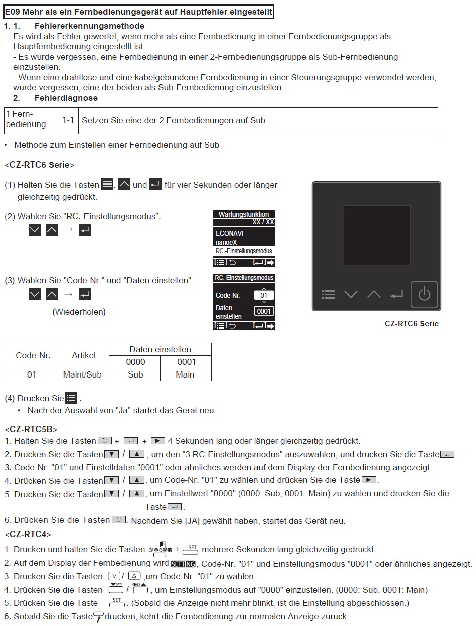
Error code E03: The remote control does not recognise a communication signal from the remote control
Possible causes:
- No remote control connected to the indoor unit.
- Remote control defective.
- Remote control connection to the indoor unit is faulty.
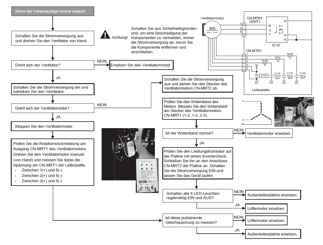
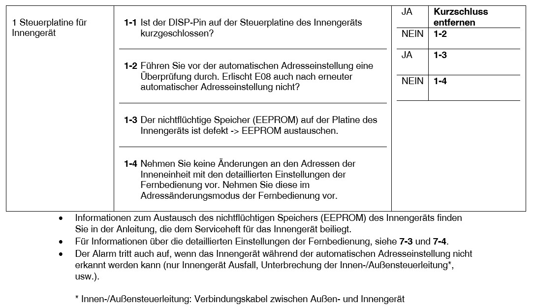
E08 Fehler bei der Einstellung einer doppelten Innengeräteadresse
1. Fehlererkennungsmethode
Es wird als Fehler gewertet, wenn die Adressen der Innengeräte doppelt vorhanden sind.
- Die Adresseinstellungen der Inneneinheit sind im detaillierten Fernbedienungseinstellungsmodus doppelt vorhanden.
- Der DISP-Stift des Mehrfachgeräts ist mit dem Innengerät, dessen Adresse nicht eingestellt ist, kurzgeschlossen.
2. Fehlerdiagnose
E14 Duplizierung der Haupteinheit im Simultanbetrieb Multi Control (Außeneinheit erkannt)
1. Fehlererkennungsmethode
Es wird als Fehler gewertet, dass die Hauptgeräte in der Innengerätegruppe doppelt vorhanden sind.
- Die Einstellung der Haupteinheit wurde in der Einstellung für die Steuerung der Innengerätegruppe im detaillierten Einstellungsmodus der Fernbedienung vorgenommen.
2. Fehlerdiagnose

E18 Fehlerhafte Kommunikation in der Verdrahtung der Gruppensteuerung
1. Fehlererkennungsmethode
Wenn die Hauptfernbedienung nicht mit einer Unterfernbedienung in der Fernbedienungsgruppe kommunizieren kann.
Es wird als Fehler gewertet, wenn eine Unterfernbedienung in einer Fernbedienungsgruppe drei Minuten lang nicht mit der Hauptfernbedienung kommunizieren kann.
- Ein Innengerät innerhalb der Steuerungsgruppe ist nicht eingeschaltet.
- Der CHK-Stift und der TEXT-Stift des Innengeräts in der Steuerungsgruppe sind kurzgeschlossen.
- Der DISP-Stift eines Innengeräts unter der Fernbedienung in der Steuerungsgruppe ist kurzgeschlossen.
- Die Verdrahtung der Fernbedienungsgruppe ist unterbrochen.
- Mehr als ein Innengerät in der Steuergruppe ist auf Haupt eingestellt.
- Ein Innengerät in der Steuergruppe ist auf "Separat" eingestellt.
2. Fehlerdiagnose


Error code E01: The remote control detects an error signal from the indoor unit
Possible causes:
The address of the indoor unit was incorrectly controlled by the unwanted remote control of the indoor unit.
Error receiving the serial communication signal. (Signal from the main indoor unit with group control)
Example: The automatic address is not complete.
Error code E02: The remote control detects an error signal from the indoor unit
Possible causes:
Serial communication signal transmission error
Error code E04: The indoor unit detects an error signal from the main outdoor unit
Possible causes:
Error receiving the serial communication signal. When the power is turned on, the number of connected indoor units does not match the set number. (Except if the R.C. address is "0".)
Error code E06: Outdoor unit receives errors from indoor unit
Alarm conditions:
Outdoor unit could not receive serial communication signals from indoor unit
Possible cause:
The power supply to the indoor unit was turned off after the first communication
An interruption or short circuit occurred in the control line between the units after the initial communication was completed
Location:
Check the power supply on the indoor and outdoor units and the control lines between the units
Notes:
This alarm is recognised after the initial communication is completed. For this reason, it does not occur if the serial port is not connected, the terminal unit is not set, or other problems have occurred before the initial communication is completed. If the initial communication has not been completed, alarm E04 occurs
Error code E12: Do not allow automatic address setting to start
Alarm conditions:
The automatic address setting started when the automatic address setting was performed on another outdoor unit in the same connection
Possible cause:
The automatic address setting is carried out on another outdoor unit
Location:
This alarm is not shown on the remote control. Therefore, check the blinking on the outdoor unit circuit board.
Correction
Wait for the automatic address setting on the outdoor unit, on which it is being performed, to finish. Then restart the automatic address setting
Error code E15: Automatic address setting alarm (too few units)
Alarm conditions:
The number of indoor units was too small when the automatic address setting was carried out
Possible causes:
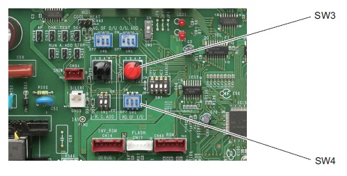
The number of indoor units set with the indoor unit quantity setting SW (SW3, SW4) on the circuit board of the outdoor unit is too high
The control lines between the indoor units have been disconnected.
Location:
Refer to the maintenance material for the test run and check the quantity setting of the indoor unit SW (SW3, SW4).
Check the control lines between the units on the indoor and outdoor units
Correction:
Perform the automatic address setting again after correcting the quantity setting of the indoor unit or the wiring between the units
Notes:
3WAY switch position
E16: Automatic address setting alarm (too many units)
Alarm conditions:
The number of indoor units was too small when the automatic address setting was carried out
After the initial communication, an unrecognised unit was recognised
Possible cause:
The number of indoor units set in the indoor unit volume setting SW (SW3, SW4) on the outdoor unit board is less than the set number
The control lines between the units are incorrectly wired
Location
Refer to the maintenance material for the test run and check the quantity setting of the indoor units
Check the control lines between the units on the indoor and outdoor units
Correction:
Perform the automatic address setting again after correcting the quantity setting of the indoor unit or the wiring between the units
Error code E20: No indoor unit during automatic address setting
Alarm conditions
No indoor units were recognised in the automatic address setting
Possible cause:
The control lines between the indoor units have been disconnected
Serial connector 1 (CN76) is not connected to the outdoor unit
The power supply is switched off on all indoor units in the system
Location:
Check whether the control lines between the units from the outdoor unit to the indoor units are interrupted
Check whether the serial connector 1 (CN76) on the outdoor unit is removed
Check the power supply to the indoor units
Correction:
Reconnect the control cable between the units from the outdoor unit to the indoor unit
Notes:
Position of the CN76 serial connector on 3-pin


Error code E24: Outdoor unit could not receive communication from another outdoor unit
Alarm conditions:
After the initial communication was completed, communication from an outdoor unit was interrupted
Possible cause:
After the first communication was completed, the control wiring between the main and secondary outdoor units was interrupted
The power supply to the outdoor unit was turned off after the first communication
Error code E25: Outdoor unit address setting error (duplicated)
Alarm conditions:
Within 3 minutes, communication was received five times or more on the main sub-control wiring of the outdoor unit with the same address as this unit
Possible cause:
The unit number is set incorrectly
Location:
Recheck the unit numbers
Notes:
Recovery from this alarm is automatic (if there is no communication with the same address for 3 minutes).
Error code E26: Incorrect number of outdoor units
Alarm conditions:
After power initialisation, the set outdoor unit quantity for 3 minutes or longer did not match the number of outdoor units recognised on the control line between the outdoor units
Possible cause:
The outdoor unit quantity is set incorrectly
The outdoor unit control cable is disconnected
Location:
Recheck the outdoor unit settings
Check the outdoor unit control lines
Correction:
Correct the incorrect outdoor unit quantity settings
Repair the outdoor unit control cable.
Notes:
The restoration after this alarm is automatic (if the set number of outdoor units matches the number of outdoor units recognised on the control line of the outdoor units).
E 29: Outdoor unit error when receiving the relay control unit
Alarm conditions:
The communication between the outdoor unit and the outdoor unit (main unit) has been interrupted for at least 3 minutes
Possible cause:
After the first communication processes were completed, the control line between the outdoor units was interrupted
After the first communication was completed, the RC connector was removed
The power supply on the outdoor unit (main unit) is turned off
Location:
Check the outdoor unit control lines
Check the RC connections
Check the power supply on the outdoor unit (main unit)
Correction
Repair the outdoor unit control cable.
Correct the RC connection
Turn on the outdoor unit (main unit)
Error code E30: Error when transmitting to the outdoor units
Possible causes:
During the automatic address setting, the number of connected devices does not correspond to the set number.
If you switch on the power supply, the number of connected devices does not correspond to the set number.
Outdoor unit serial transmission error
Error code E31: Wiring error between the circuit boards
Possible cause: When does it happen?
- An error occurred while rewriting the microcomputer
- If the device is switched off while rewriting the microcomputer
- Without wiring between the board and the ROM burner
Location:
Rewrite the micro-computer
Turn the unit on again
Correction:
Replace control board
Error code F04: Error in the compressor 1 outlet temperature
Alarm conditions:
Discharge temp. of 100°C or higher was found 30 minutes or more after the compressor stopped
Discharge temp. of 80°C or higher was found after all compressors were stopped for 60 minutes or longer
A / D step is 10 steps or less (short circuit)
Possible cause:
1. Malfunction of the sensor
- Malfunction of the sensor element
- The sensor wiring is partially disconnected, which leads to increased electrical resistance
- This alarm does not occur if the wiring is interrupted or the plug is not connected to the circuit board of the outdoor unit
2. Wiring crossed or installation failure
- The outlet temperature sensor of this compressor is connected to the outlet pipe of the other compressor
- The connector for the outlet temperature sensor of the problem compressor is connected to the PCB connector of the outdoor unit for the other compressor
3. Circuit board fault in the outdoor unit
4. The check valve on the outlet pipe for this compressor is wet
5. An air short circuit blockage in the area of the outdoor unit raised the ambient temperature of the outdoor unit and reduced the cooling effects after the compressor stopped
6. There is a cause that leads to a P03, P17 or P02 alarm
7. Electrical noise
Location:
1. Malfunction of the sensor and failure of the outdoor unit circuit board
- Constantly shows a high temperature
- If monitoring software or other means of monitoring are used, the discharge temperature can fluctuate suddenly and wildly in some cases
- In some cases the exact temperature may not be known, even if surveillance software is used
Error code F04: Error in the compressor 2 outlet temperature
Alarm conditions:
Discharge temp. of 100°C or higher was found 30 minutes or more after the compressor stopped
Discharge temp. of 80°C or higher was found after all compressors were stopped for 60 minutes or longer
A / D step is 10 steps or less (short circuit)
Possible cause:
1. Malfunction of the sensor
- Malfunction of the sensor element
- The sensor wiring is partially disconnected, which leads to increased electrical resistance
- This alarm does not occur if the wiring is interrupted or the plug is not connected to the circuit board of the outdoor unit
2. Wiring crossed or installation failure
- The outlet temperature sensor of this compressor is connected to the outlet pipe of the other compressor
- The connector for the outlet temperature sensor of the problem compressor is connected to the PCB connector of the outdoor unit for the other compressor
3. Circuit board fault in the outdoor unit
4. The check valve on the outlet pipe for this compressor is wet
5. An air short circuit blockage in the area of the outdoor unit raised the ambient temperature of the outdoor unit and reduced the cooling effects after the compressor stopped
6. There is a cause that leads to a P03, P17 or P02 alarm
7. Electrical noise
Location:
1. Malfunction of the sensor and failure of the outdoor unit circuit board
- Constantly shows a high temperature
- If monitoring software or other means of monitoring are used, the discharge temperature can fluctuate suddenly and wildly in some cases
- In some cases the exact temperature may not be known, even if surveillance software is used
Error code F06: Outdoor unit heat exchanger 1 gas (inlet) temperature sensor faulty
Alarm conditions:
- A / D step is 10 steps or less (short circuit)
- A / D step is 1014 steps or more (open circuit)
Possible cause:
- Default of the sensor (including connector)
- PCB fault
Location:
- Measure the sensor resistance. Check whether the sensor is functioning normally
- Use a remote control or PC monitor to check the temperature detected by the microcomputer.
Error code F07: Outdoor unit heat exchanger 1 liquid temperature sensor (outlet) faulty
Alarm conditions:
A / D step is 10 steps or less (short circuit)
A / D step is 1014 steps or more (open circuit)
Possible cause:
Sensor malfunction (including connector)
Circuit board fault
Location:
Measure sensor resistance. Check whether the sensor is functioning normally
Use a remote control or PC monitor to check the temperature detected by the microcomputer
Error code F08: Outside temperature sensor faulty
Alarm conditions:
A / D step is 10 steps or less (short circuit)
A / D step is 1014 steps or more (open circuit)
Possible cause:
Sensor malfunction (including connector)
PCB fault
Location:
Measure sensor resistance. Check whether the sensor is functioning normally
Use a remote control or PC monitor to check the temperature detected by the microcomputer
Error code F12: Compressor inlet temperature sensor faulty
Alarm conditions:
A / D step is 10 steps or less (short circuit)
A / D step is 1014 steps or more (open circuit)
Possible cause:
Sensor malfunction (including connector)
PCB fault
Location:
Measure sensor resistance. Check whether the sensor is functioning normally
Use a remote control or PC monitor to check the temperature detected by the microcomputer
Error code F14: Overcooling gas temperature sensor faulty
Alarm conditions:
A / D step is 10 steps or less (short circuit)
A / D step is 1014 steps or more (open circuit)
Possible cause:
Sensor malfunction (including connector)
PCB fault
Location:
Measure sensor resistance. Check whether the sensor is functioning normally
Use a remote control or PC monitor to check the temperature detected by the microcomputer
Error code F16: High pressure sensor faulty, high load
Alarm conditions:
High pressure sensor not connected or open circuit
The high pressure sensor continuously measured over 3.6 MPa for 30 minutes while the outdoor units stopped
High pressure sensor detected over 3.6 MPa while outdoor units were operating
(In some cases, start and stop may be repeated due to the pre-trigger mode.)
Possible cause
Defective high pressure sensor
Error connecting the connector to the outdoor unit circuit board
Error when the service valve in the outdoor unit opened
Blocked refrigerant circuit
Refrigerant overfilled
Circuit board fault in the outdoor unit
Location:
1. High pressure sensor failure
Check the sensor resistance value. (use a tester and measure the resistance between sensor No1 and No3)
- A resistance of less than 95 kΩ indicates a short circuit or other problems
- A resistance of 95 kΩ - 105 kΩ (low pressure sensor pin 1-3) is normal
- A resistance of more than 105 kΩ indicates an interruption or other fault
Connect a pressure gauge to the low pressure outlet and check whether the value displayed by the monitoring software has changed and whether the pressure gauge pressure deviates significantly
During heating, check whether the temperature is below the highest temperature of the indoor unit E1
The pressure detected by the high pressure sensor is the highest pressure in the system. Therefore, the converted saturation temperature during heating will never be lower than the indoor unit’s E1 temperature. During cooling, this temperature is never lower than the outdoor unit fluid temperature
2. Error connecting the connector to the outdoor unit circuit board
Check the connector connected to the outdoor unit circuit board
3. The service valve cannot be opened
Check the open/closes condition of the valve
4. Check the refrigerant circuit for blockages
5. Check if the refrigerant is overfilled
In the event of blockage or overloading, refrigerant can accumulate in the outdoor unit (cooling) and in the indoor unit (heating). Sometimes there may be a sudden increase in pressure at start-up
6. Circuit board fault in the outdoor unit
The control points are the same as in the case of a malfunction of the high pressure sensor.
A normal PCB is needed to determine if the problem is a PCB fault or malfunction of the pressure sensor. If an abnormality of the high pressure sensor malfunctions is found in the test objects, first try to replace the circuit board and test again
The problem has been rectified: Outdoor unit circuit board error
The fault is not eliminated: High pressure sensor fault
Correction
1. Replace the high pressure sensor
When you replace a high pressure sensor, perform the refrigerant recovery of the outdoor unit
2. Replace circuit board
3. Rectify the refrigerant circuit fault
Open the outdoor unit valve
Clear blockage
If the refrigerant is overfilled, collect the appropriate amount of refrigerant
∗ Overloading standards. Install and check the manometer on the high pressure distance connector of the outdoor units
during cooling: Not available when the outdoor temperature is low or the outdoor fan is set. While both compressors 1 and 2 work in the blower mode with 12 or 13 steps, the saturation temperature of the high pressure indicates the outside temperature
+ around 15°C. If the temperature is 5°C above the specified temperature, an overload can be expected
During heating: In an indoor unit, the refrigerant flow is poor (E1 temperature and outlet temperature are low), and the mechanical valve of this device is open for at least 300 pulses and the E1 temperature is close to room temperature. However, note that this type of data often occurs when there is a height difference between indoor units. Reducing the amount of refrigerant improves the flow of refrigerant, but reducing it too much increases the likelihood of alarms related to low oil level (roller side), low pressure SW and outlet temperature. Act with caution
Notes:
Example: A malfunction had occurred when the fluid, suction and pressure pipes were blocked
Error code F17: Low pressure sensor faulty
Alarm conditions:
Sensor short circuit
Open sensor circuit
Possible cause:
Sensor malfunction (including connector)
PCB fault
Location:
Measure sensor resistance. Check whether the sensor is functioning normally
Use a remote control or PC monitor to check the temperature detected by the microcomputer
Error code F23: Outdoor unit heat exchanger 2 gas (inlet) temperature sensor faulty
Alarm conditions:
- A / D step is 10 steps or less (short circuit)
- A / D step is 1014 steps or more (open circuit)
Possible cause:
- Sensor malfunction (including connector)
- PCB fault
Location:
- Measure sensor resistance. Check whether the sensor is functioning normally
- Use a remote control or PC monitor to check the temperature detected by the microcomputer.
Error code F24: Outdoor unit heat exchanger 2 liquid temperature sensor (outlet) faulty
Alarm conditions:
A / D step is 10 steps or less (short circuit)
A / D step is 1014 steps or more (open circuit)
Possible cause:
Sensor malfunction (including connector)
Circuit board fault
Location:
Measure sensor resistance. Check whether the sensor is functioning normally
Use a remote control or PC monitor to check the temperature detected by the microcomputer
Error code F31: Error in the outdoor unit solid-state memory (EEPROM)
Alarm conditions:
There is no solid-state memory available for power initialisation
The read values do not match after writing to the solid-state memory is complete
Possible cause:
Memory was not inserted after the circuit board was replaced
The service life of the solid-state memory has been reached
The solid-state memory is installed incorrectly (wrong direction, bent pin, etc)
Location:
Check the solid-state memory on the circuit board
Error code H01: Compressor 1 current values not in the control range (overcurrent)
Alarm conditions:
The primary current of compressor 1 (INV) has detected an overcurrent that is higher than the values listed in the following table (overcurrent)
| Unit performance | 8 HP | 10 HP | 12 HP | 14 HP |
| Actual (A) | 15.1 | 19.8 | 21.0 | 21.0 |
Possible cause:
Wiring error
Operation under extremely high pressure (overloaded operation)
Power source and voltage failure (sudden voltage drop)
Location:
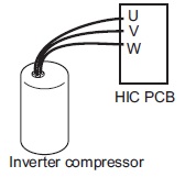
1. Wiring error
Check whether the connection between "HIC PCB" and "Inverter Compressor" is faulty. See Figure
2. Operation under extremely high pressure (overloaded operation)
Error opening the service valve of the outdoor unit. Check the open/closed condition of the outdoor unit’s maintenance valve
High pressure sensor performance map difference (under-shift)
Connect a pressure gauge to the high pressure outlet and check whether the value displayed by the monitoring software has changed and whether the pressure gauge pressure deviates significantly
3. Check the power supply and the voltage
Correction:
1. Wiring error
Loosen the wiring and rectify wiring error
2. Operation under extremely high pressure (overloaded operation)
Open the outdoor unit service valve
Replace high pressure sensor
When you replace a high pressure sensor, perform the refrigerant recovery of the outdoor unit
3. Improvement of the current source and the voltage
Error code H03: CT sensor for compressor 1 not connected, short circuit
Alarm conditions:
Compressor 1: When compressor 1 (INV) is stopped, the primary current is sensed above 18A. * If the frequency of compressor 1 (INV) is above 35 Hz and the secondary current is above 7.0 A, a primary current of less than 0.7 A is detected
* No current is recognised even though the compressors are operating
Possible cause:
Transformer circuit failure (including cable break etc.)
Transformer circuit plug removed
Phase missing to which the current transformer circuit is connected
This transformer circuit is connected to the connection of the other transformer circuit
PCB error
Electrical noise
Location:
1. CT circuit failure, PCB failure
Problem: The current value during compressor operation is below the threshold.
Test:
Make sure that the plug is not removed
Check the continuity of the transformer circuit.
Install a normal transformer instead of this transformer and check it. If current is detected, the circuit board can be judged to be OK -> transformer fault
• Check whether current flows in the phase to which the current transformer circuit is connected -> Check the voltage and the current
2. Crossed wiring or installation error
Problem: If the compressor is stopped, the actual value on the other compressor is high. ☆ If this type of condition occurs, the recording of the occupancy has priority.
3. If after checking the above items the cause is still unknown, it is possible that the noise is the cause of the problem. It is necessary to connect a PC or other instrument.
Correction:
Replace the transformer circuit
Replace the outdoor unit circuit board.
Rectify the problem
Notes:
Example: The connector was not inserted after the circuit board was replaced.
Use a normal current transformer as an aid to determine whether the problem is a circuit board fault or a transformer fault.
Error code H05: Compressor 1 outlet temperature sensor not connected
Alarm conditions:
This alarm occurs when the temperature sensor of the discharge sensor is not inserted in the sensor holder of the tube or when the sensor itself malfunctions other than as a cut wire
At an outside air temperature of -10°C or higher: An alarm is triggered if the temperature detected by the outlet sensor has changed by less than 2°C, if the compressor has been in operation for 10 minutes immediately after starting.
If the outside air temperature is lower than -10°C: An alarm is triggered if the temperature detected by the outlet sensor has changed by less than 2°C, if the compressor has been in operation for 30 minutes immediately after starting.
Possible cause:
The detector for the temperature of the discharge sensor is not inserted in the sensor holder of the tube
The discharge sensor itself has a different malfunction to a cut wire
Location:
Check whether the outlet temperature sensor is inserted in the sensor holder
Make sure that enough thermally conductive putty is applied.
Remove the discharge sensor from the sensor holder and expose the sensor to outside air for about 5 minutes. Make sure that the temperature detected by the sensor adapts to the outside air temperature. (However, the sensor cannot detect temperatures at or below 0°C.)
Correction:
Place the sensor in the holder and apply sufficient heat-conductive putty.
If the sensor is defective, replace it
Error code H06: Low pressure uncontrolled pressure drop
Alarm conditions:
The low pressure sensor continuously detects less than 0.06 MPa for 2 minutes or less than 0.02 MPa for a moment
Possible cause:
Defective low pressure sensor
Error when the service valve in the outdoor unit opened
Blocked refrigerant circuit
Lack of refrigerant gas
Refrigerant accumulates in the stopped outdoor units
Location:
1. Low pressure sensor defective
Check the sensor resistance value (use a tester and measure the resistance between sensor No1 and No3)
- A resistance of less than 95 kΩ indicates a short circuit or other problems
- A resistance of 95 kΩ - 105 kΩ (low pressure sensor pin 1-3) is normal
- A resistance of more than 105 kΩ indicates an interruption or other fault
Connect a pressure gauge to the low pressure outlet and check whether the value displayed by the monitoring software has changed and whether the pressure gauge pressure deviates significantly
2. The outdoor unit service valve can not be opened
Check the open/closed condition of the maintenance valve
3. Check the refrigerant circuit for blockages
If the refrigerant circuit is blocked, the refrigerant will not return to the compressor. As a result, the vacuum may occasionally decrease abnormally. Then check the following points: Solenoid valve, expansion valve, stains caused by dirty water in the circuit, etc
4. Lack of refrigerant gas
If there is a lack of refrigerant charge or amount in the system caused by gas leakage, the low pressure may occasionally decrease abnormally
5. Refrigerant is accumulated in the stop mode of the outdoor units
Leakage of expansion valve and solenoid valve in the outdoor unit in stop mode, etc
Correction:
1. Replace the low pressure sensor
If you replace a low pressure sensor, perform the refrigerant recovery on the outdoor unit
2. Rectify the refrigerant circuit fault
Open the outdoor unit valve
Clear blockage
Resolve insufficient refrigerant gas (correction of gas leakage, additional refrigerant, etc.)
If you top up due to lack of refrigerant, gradually add 500 g of refrigerant each time
Notes:
Example:
The alarm had occurred due to a lack of refrigerant due to a gas leak
The alarm occurred when the fluid, suction and pressure pipes were blocked
Error code H08: Fault (open circuit) on the oil sensor (connection) on the compressor 1
Alarm conditions:
This alarm occurs when a connection (pins 1 and 2 for compressor 1, pin 4 and 5 for compressor 2) is open.
Possible cause:
Plug removed
Location:
Check whether the connector is firmly connected
Correction:
Connect the plug
Correct the connection on pins 4 and 5
Error code H11: Compressor 2 current values incorrect (overcurrent)
Alarm conditions:
During operation, the compressor current exceeded 12 A for at least 30 seconds. However, this alarm is not recognised 4 seconds after the compressor startsPossible cause:
- Compressor failure (blocked or partially blocked)
- Transformer fault (including cable break)
- Missing power phase
- Low voltage
- PCB error
Location:
1. Compressor failure (partially locked)
Problem: The actual value during operation considerably exceeds the value given above.
Test: If the current for each phase is measured with a clamp meter or similar instrument, check that the current value for all phases is not high. If MG has been switched on (caution), make sure that no compressor noises occur or that the compressor does not run with a groaning noise.
2. CT circuit failure, PCB failure
- Check for bad connector contact
- Check continuity of the transformer circuit
- Install a normal transformer instead of this transformer and check it. If current is detected, the board can be repaired → CT circuit failure
- Check whether current flows in the phase to which the transformer circuit is connected -> Check the voltage and the current
3. Missing power phase
Problem: This alarm mainly occurs when the T phase is missing. If the R phase or S phase is missing, transformer or PCB continuity problems arise. However, this may not apply in the event of a missing phase caused by a magnetic SW error.
Check: There is a possibility of a magnetic SW error. Therefore, check the phase voltage in a location as close as possible to the compressor.
4. Low voltage
Problem: In most cases, this occurs when another constant speed compressor (including compressors in other units) or another unit is started. This also occurs when the power cables are extremely long.
Test: Check the voltage between the individual phases. However, if this occurs when starting other units or compressors, an oscilloscope is required.
5. PCB error
Test: Make sure that the current value measured with the clamp meter is not below the value measured with the PC or the remote control
6. If after checking the above items the cause is still unknown, it is possible that noise is the cause of the problem. It is necessary to connect a PC or other instrument
Correction:
- Replace the compressor
- Replace the transformer circuit
- Repair the circuit
- Adjust the primary side power. Repair the power cables
- Replace the outdoor unit circuit board
- Rectify the fault
In the event of a compressor failure, measures may need to be taken to remedy the cause of the compressor failure (e.g., fluid blockage) to prevent a new occurrence. Make sure that there is no cause for the compressor blocking
Error code H13: CT sensor for compressor 2 not connected, short circuit
Error code H03: CT sensor for compressor 1 not connected, short circuit
Alarm conditions:
Compressor 2: The current value on compressor 2 is less than 2.0 A after 2 seconds or more have passed after the compressors started operating and performing.
Possible cause:
Transformer circuit failure (including cable break etc.)
Transformer circuit plug removed
Phase missing to which the current transformer circuit is connected
This transformer circuit is connected to the connection of the other transformer circuit
PCB error
Electrical noise
Location:
1. CT circuit failure, PCB failure
Problem: The current value during compressor operation is below the threshold.
Check:
- Make sure that the plug is not disconnected
- Check the continuity of the current transformer circuit
- Install a normal current transformer instead of this current transformer and check it. If current is detected, the circuit board can be assessed as OK -> transformer fault
- Check whether current flows in the phase to which the transformer circuit is connected -> Check the voltage and the current
2. Crossed wiring or installation error
Problem: If the compressor is stopped, the actual value on the other compressor is high. ☆ If this type of condition occurs, the recording of the occupancy has priority.
3. If after checking the above items the cause is still unknown, it is possible that the noise is the cause of the problem. It is necessary to connect a PC or other instrument.
Correction:
- Replace the transformer circuit
- Replace the outdoor unit circuit board
- Rectify the problem
Notes:
example: The connector was not inserted after the circuit board was replaced.
Use a normal current transformer as an aid to determine whether the problem is a circuit board fault or a transformer fault.
Error code H15: Compressor 2 outlet temperature sensor not connected
Alarm conditions:
This alarm occurs when the temperature sensor of the discharge sensor is not inserted in the sensor holder of the tube or when the sensor itself malfunctions other than as a cut wire
At an outside air temperature of -10°C or higher: An alarm is triggered if the temperature detected by the outlet sensor has changed by less than 2°C, if the compressor has been in operation for 10 minutes immediately after starting.
If the outside air temperature is lower than -10°C: An alarm is triggered if the temperature detected by the outlet sensor has changed by less than 2°C, if the compressor has been in operation for 30 minutes immediately after starting.
Possible cause:
The detector for the temperature of the discharge sensor is not inserted in the sensor holder of the tube
The discharge sensor itself has a different malfunction to a cut wire
Location:
Check whether the outlet temperature sensor is inserted in the sensor holder
Make sure that enough thermally conductive putty is applied.
Remove the discharge sensor from the sensor holder and expose the sensor to outside air for about 5 minutes. Make sure that the temperature detected by the sensor adapts to the outside air temperature. (However, the sensor cannot detect temperatures at or below 0°C.)
Correction:
Place the sensor in the holder and apply sufficient heat-conductive putty.
If the sensor is defective, replace it
Error code H21: Compressor 2 HIC Alarm
Alarm conditions
During operation, the compressor current exceeded 14 A for at least 4 seconds. However, this alarm is not recognised 2 seconds after the compressor starts
Possible cause:
- Compressor failure (blocked or partially blocked)
- Transformer fault (including cable break)
- Missing power phase
- Low voltage
- PCB error
Location:
1. Compressor failure (partially locked)
Problem: The actual value during operation considerably exceeds the value given above.
Test: If the current for each phase is measured with a clamp meter or similar instrument, check that the current value for all phases is not high. If MG has been switched on (caution), make sure that no compressor noises occur or that the compressor does not run with a groaning noise.
2. CT circuit failure, PCB failure
- Check for bad connector contact
- Check continuity of the transformer circuit
- Install a normal transformer instead of this transformer and check it. If current is detected, the board can be repaired → CT circuit failure
- Check whether current flows in the phase to which the transformer circuit is connected -> Check the voltage and the current
3. Missing power phase
Problem: This alarm mainly occurs when the T phase is missing. If the R phase or S phase is missing, transformer or PCB continuity problems arise. However, this may not apply in the event of a missing phase caused by a magnetic SW error.
Check: There is a possibility of a magnetic SW error. Therefore, check the phase voltage in a location as close as possible to the compressor.
4. Low voltage
Problem: In most cases, this occurs when another constant speed compressor (including compressors in other units) or another unit is started. This also occurs when the power cables are extremely long.
Test: Check the voltage between the individual phases. However, if this occurs when starting other units or compressors, an oscilloscope is required.
5. PCB error
Test: Make sure that the current value measured with the clamp meter is not below the value measured with the PC or the remote control
6. If after checking the above items the cause is still unknown, it is possible that noise is the cause of the problem. It is necessary to connect a PC or other instrument
Correction:
- Replace the compressor
- Replace the transformer circuit
- Repair the circuit
- Adjust the primary side power. Repair the power cables
- Replace the outdoor unit board
- Rectify the fault
In the event of a compressor failure, measures may need to be taken to remedy the cause of the compressor failure (e.g., fluid blockage) to prevent a new occurrence. Make sure that there is no cause for the compressor blocking
Error code H27: Compressor 2 Oil detection sensor (connection) defective
Alarm conditions:
This alarm occurs when a connection (pins 4 and 5 for compressor 2) is open.
Possible cause:
Plug removed
Location:
Check whether the connector is firmly connected
Correction:
Connect the plug
Correct the connection on pins 4 and 5
Error code H31: Compressor 1 HIC Alarm
Alarm conditions:
This alarm occurs when the microcomputer detects an error signal (indicating an abnormal HIC temperature or other problems) from the HIC.
The HIC assesses the current and the temperature and outputs the error signal. In general, this indicates problems with the HIC itself.
Possible causes:
Overcurrent in the HIC circuit and the resulting abnormal warming caused by a HIC error
Location:
Check the power and connector wiring. If the wiring and connections are normal, use a tester to measure the resistance between the HIC performance of the compressor (HIC +) and ground (HIC–). In the event of a short circuit, there is a HIC malfunction.
Check the figure below
Correction:
If a HIC error is found, replace the board
Notes:
Switch off the power supply and check the continuity of HIC + and HIC– on the HIC board
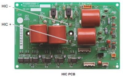
Error code L04: The address settings of the outdoor unit have been duplicated
Alarm conditions:
Within 3 minutes, communication was received five times or more via the control wiring between the units containing the same address as this unit
Possible cause:
Incorrect outdoor system address settings
Location:
Recheck the system address settings
Correction:
Correct the system address settings
Notes:
Restoration after this alarm is automatic (if the communication containing the same address as this device is not received 3 minutes after detection).
Error code L05: Priority of indoor unit duplicated (For indoor priority)
Alarm conditions:
Remote control without priority setting
Possible causes:
There are 2 or more indoor unit controls that take precedence over the operating mode in the refrigerant circuit.
Error code L05: Indoor unit double prioritised (not for prioritised indoor) and outdoor unit
Alarm conditions:
Remote control with priority set
Possible causes:
There are 2 or more indoor unit controls that take precedence over the operating mode in the refrigerant circuit.
Error code L10: The capacity of the outdoor unit was not set
Alarm conditions:
The capacity of the outdoor unit has not been set or the setting is not allowed by the system
Location:
Connect the remote control for maintenance of the outdoor unit. On the outdoor unit detailed EEPROM setting mode screen, check the outdoor unit capacity value (item code 81). Make sure it is not set to "0" or a capacity that is not allowed.
Correction:
If article code 81 is incorrect, use the remote control to maintain the outdoor unit and set it properly.
After changing the setting, make sure that you reset both the indoor and outdoor voltage
Notes:
The remote controller for maintenance of the outdoor unit is required to set the refrigerant type in the EEPROM of the outdoor unit.
Error code L17: Outdoor unit model not matching
Alarm conditions:
This alarm occurs when a unit other than a R410A refrigerant unit is connected
Possible cause :
A refrigerant unit R407C or a model R22 unit was accidentally connected
The connected unit is correct, but the refrigerant type setting in the outdoor unit's EEPROM (item code 80) is incorrect.

Location:

Check the type of refrigerant on the connected unit
Use the remote control to maintain the outdoor unit and check the refrigerant with article number 80. If the setting is incorrect, change it in R410A

Notes:
The remote control for maintenance of the outdoor unit is required to set the refrigerant type in the EEPROM of the outdoor unit.
Error code L18: 4-way valve spool separated, line separated
Alarm conditions:
During heating mode (comp. ON), the highest detected temperature on a heat exchanger of the outdoor unit (EXG 1, EXG 2, EXL 1 or EXL 2) was 20°C or more above the outside air temperature (air temp.) continuously for 5 minutes or longer or the recorded intake temperature (SCT) was 20°C or more above the outside air temperature continuously for 5 minutes or longer.
Possible causes:
The 4-way valve connector (20S CN022) was disconnected from the control board
The 4-way valve circuit is blocked (fault)
Location:
Check the 4-way valve connector (20S CN022)
If the connector is normal, check the 4-way valve wiring and the PCB circuit
Correction:
If the connector is normal, correct or replace the problem areas
Error code P03: Error in the compressor 1 outlet temperature
Alarm conditions:
The temperature is 106°C or more and there was a stop before triggering.
The alarm occurs when the stop occurs more than once before triggering. However, the flow counter is cleared if the compressor runs continuously for a certain period of time.
Possible causes
- Blockage of the liquid valve capillaries
- Insufficient amount of refrigerant (including problems due to insufficient initial charge and gas leakage)
- Blocking of low-pressure parts through the penetration of foreign bodies (moisture, scale, etc.)
- Crossing (hose or circuit board connector) with the other compressor thermistor
- Malfunction of the expansion valve
- Accumulation of refrigerant on stopped outdoor units
- Sensor for compressor discharge defective
- PCB- Error (A / D conversion error)
- Electrical noise
Location:
1. Capillary blockage
Problem: The compressor outlet temperature does not drop even if the fluid valve is switched on.
Control: If the fluid valve is in operation and the fluid valve is switched on, check whether the secondary side of the fluid capillaries is cold.
2. Too little refrigerant
Problem: The fluid effect is bad
Test: Check whether or not the superheat temperature drops when the mechanical valve of the evaporator is opened to 300 pulses or more (after checking for foreign matter).
3. Contamination by foreign bodies
Problem: The effectiveness of the fluid valve is poor
Control: Make sure that there is no difference in condensation or frost conditions between the primary and secondary tubes of the strainer.
4. Crossed thermistor
Problem: The outlet temperature of the other compressor is high, although only this compressor is in operation
When the fluid valve turns on, the outlet temperature of the other compressor drops.
5. Accumulation of refrigerant in stopped outdoor units
Problem:
- The system is OK when all outdoor units are in operation. However, when a specific outdoor unit is stopped, symptoms of insufficient gas supply appear
- Condensation or frost is visible up to the top of the accumulator of the stopped outdoor unit
- After stopping an outdoor unit, the sound that refrigerant flows into an outdoor unit that lasts for a long time is heard
- If an outdoor unit starts after a long period, the startup is accompanied by strong vibrations
Check:
Representative parts are the liquid capillaries (the secondary side of the capillaries is cool during cooling operation), the mechanical valve, the mechanical valve bypass check valve (refrigerant flow noise can be heard and stops when the liquid valve is closed) and the hot gas defrost valve (if the secondary valve side is still hot after a long period of time, be careful not to confuse the transferred heat with a valve failure.)
Ice grows on the lower parts of some heat exchangers for outdoor units, but not on others. Because this problem can also occur with outdoor units with a high operating speed under conditions with insufficient gas, caution should be exercised.
6. Sensor defective
Test:
- This alarm is likely to occur when the wiring is partially broken. (It is difficult to identify even if the continuity is checked.) The detected discharge temperature is high
- Although such conditions rarely occur, a P02 alarm is likely when the detected discharge temperature is low
- Replace the sensor with another discharge sensor and compare the temperature conditions
7. If the cause is not known after checking the above points, it is possible that the electrical noise is the cause of the fault.
Correction
- Replace the sensor.
- Replace the outdoor unit circuit board.
- Correct the problem areas.
Notes:
Example: All possible causes
Works continuously for a set period of time
Shows 2.5 minutes or more for an inverter unit and 30 seconds or more for a constant speed compressor
Error code P04: Operation of the high pressure switch
Alarm conditions:
The operation of the electronic circuit in the high pressure switch can short-circuit the connection depending on the pressure. The terminal is short-circuited at a pressure of 3.3 MPa or more. As soon as the connection is short-circuited, it remains in this state until the pressure drops below 2.6 MPa
Possible cause:
- Failure of the check valve in the pressure pipe of the compressor
- The service valve is closed
- Blockage of the outdoor heat exchanger when cooling down
- An air short in the outdoor unit while cooling down
- External fan failure during cooling
- Blockage of the air filter in the indoor unit while heating
- Air short circuit in the indoor unit during heating
- Internal fan failure when heating
- Refrigerant circuit blockage
- Mechanical valve failure
- Failure of the solenoid valve set
- Too much refrigerant has been charged
- High pressure switch failure
Location:
- Make sure that the high pressure switch connector is correctly connected
- When the high pressure switch is properly connected, connect a high pressure manometer to the high pressure outlet and monitor the pressure during operation to check the pressure when the high pressure switch is activated. The check valve is likely to fail if the pressure is less than 3.3 MPa. The following describes tests that must be carried out at high pressure
- While cooling down, check whether the heat exchanger of the outdoor unit is blocked. Remove any foreign objects that obstruct ventilation
- While cooling down, check whether an air short has occurred in the outdoor unit. The system works normally unless the temperature around the outdoor unit is too high.
- While cooling down, check whether the outdoor fan is defective. Check whether the screws securing the fan are loose and that the fan connector on the outdoor unit PCB is properly connected.
- While heating, check whether the air filters in the indoor unit are blocked. If it is blocked, clean the filter
- While heating, check whether there is an air short in the indoor unit. The system works normally unless the temperature around the outdoor unit is too high.
- While cooling down, check whether the outdoor fan is defective.
- Check if the refrigerant circuit is blocked. Check that all service valves are closed. Check whether the welds are blocked
- Check whether the mechanical valve is defective. Check if the mechanical valves cause rattling when resetting the power supply. Since the mechanical valve in the indoor unit is in a place that makes it difficult to test by ear, use an electrical device for testing. Check that the mechanical valve connector pin on the board outputs 4V. Also check that the coil resistance of the mechanical valve is several tens Ω.
- Check if the solenoid valve set is defective. Removing a coil that is switched on results in a clicking sound. If you remove a coil that is turned off, no such noise will be generated
- Check whether the refrigerant has been overcharged. Too much refrigerant has been charged when the subcooling temperature of the condenser is 15°C or higher.
Correction
Replace damaged components and correct the amount of refrigerant charged
Error code P05: Open phase detection for compressor 1
Alarm conditions:
This alarm occurs when a phase reversal or a missing phase is detected in phases L1-L2-L3-N
Possible cause:
Reversed phase or missing phase in phases L1-L2-L3-N
Location:
Check the cabling on the power terminal plate
Correction:
Swap the phases and reinsert them. Check if the result is in order
Error code P11: Cooling water frozen (chiller)
Error code P14: Activation of the O2sensor
Alarm conditions:
An error is evaluated if the outdoor unit receives the "O2 Alarm Generated" signal from the indoor unit
If the EEPROM setting of the indoor unit (item code 0B) is set to 0001, the EXCT input short-circuited
Correction:
1. System configuration Is an O2 sensor being used?
If YES, see 3.
If NO, see 2.
2. Internal EEPROM setting
Is the EEPROM setting, item code 0B, on the internal control card set to 001?
If YES see 3. after the change.
If NO, see 4.
3. EXCT wiring
Is the EXCT socket (cable) short-circuited?
If YES, change the wiring.
If NO, see 4.
4. Internal control card
Is the alarm triggered when the EXCT connector (cable) is disconnected and the power supply is reset? If YES, see 4-c. If NO, see 4-b.
As there is no error, see what happens
Internal control card defective -> Replace circuit board
Error code P15: Compressor 2 open phase detection
Error code P16: Compressor 1 secondary overcurrent
Alarm conditions:
This alarm occurs when a current fault or current detection fault occurs (when a fault judgment current is detected in the primary or secondary current or when an instantaneous secondary current of 18 A * or higher is detected).
* Changed, to output errors from current regardless of the frequency of the inverter. There are also 6 HP and 10 HP compressors
1. If more than the overcurrent values in the primary and secondary current specified in the table have been determined.
6TE compressors:
Primary 18A
Secondary stage 18A
10HP compressors:
Primary 21A
Secondary 21A
2. If more than the current values specified in the table are immediately detected in the secondary current.
6 HP compressors: Secondary 28A
10 HP compressors: Secondary 36A
Possible causes
There is a strong possibility of a compressor failure.
An alarm for current detection problems occurs when it is determined that no current is flowing after the start (DCCT is damaged). In this case, the cause is a DCCT error.
Location:
Check the power and connector wiring.
Correction
It is possible to solve this problem by limiting the maximum frequency.
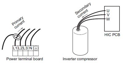
Error code P17: Error in the compressor 2 outlet temperature
Alarm conditions:
The temperature is 106°C or more and there was a stop before triggering.
The alarm occurs when the stop occurs more than once before triggering. However, the flow counter is cleared if the compressor runs continuously for a certain period of time.
Possible causes
- Blockage of the liquid valve capillaries
- Insufficient amount of refrigerant (including problems due to insufficient initial charge and gas leakage)
- Blocking of low-pressure parts through the penetration of foreign bodies (moisture, scale, etc.)
- Crossing (hose or circuit board connector) with the other compressor thermistor
- Malfunction of the expansion valve
- Accumulation of refrigerant on stopped outdoor units
- Sensor for compressor discharge defective
- PCB- Error (A / D conversion error)
- Electrical noise
Location:
1. Capillary blockage
Problem: The compressor outlet temperature does not drop even if the fluid valve is switched on.
Control: If the fluid valve is in operation and the fluid valve is switched on, check whether the secondary side of the fluid capillaries is cold.
2. Too little refrigerant
Problem: The fluid effect is bad
Test: Check whether or not the superheat temperature drops when the mechanical valve of the evaporator is opened to 300 pulses or more (after checking for foreign matter).
3. Contamination by foreign bodies
Problem: The effectiveness of the fluid valve is poor
Control: Make sure that there is no difference in condensation or frost conditions between the primary and secondary tubes of the strainer.
4. Crossed thermistor
Problem: The outlet temperature of the other compressor is high, although only this compressor is in operation
When the fluid valve turns on, the outlet temperature of the other compressor drops.
5. Accumulation of refrigerant in stopped outdoor units
Problem:
- The system is OK when all outdoor units are in operation. However, when a specific outdoor unit is stopped, symptoms of insufficient gas supply appear
- Condensation or frost is visible up to the top of the accumulator of the stopped outdoor unit
- After stopping an outdoor unit, the sound that refrigerant flows into an outdoor unit that lasts for a long time is heard
- If an outdoor unit starts after a long period, the startup is accompanied by strong vibrations
Check:
Representative parts are the liquid capillaries (the secondary side of the capillaries is cool during cooling operation), the mechanical valve, the mechanical valve bypass check valve (refrigerant flow noise can be heard and stops when the liquid valve is closed) and the hot gas defrost valve (if the secondary valve side is still hot after a long period of time, be careful not to confuse the transferred heat with a valve failure.)
Ice grows on the lower parts of some heat exchangers for outdoor units, but not on others. Because this problem can also occur with outdoor units with a high operating speed under conditions with insufficient gas, caution should be exercised.
6. Sensor defective
Test:
- This alarm is likely to occur when the wiring is partially broken. (It is difficult to identify even if the continuity is checked.) The detected discharge temperature is high
- Although such conditions rarely occur, a P02 alarm is likely when the detected discharge temperature is low
- Replace the sensor with another discharge sensor and compare the temperature conditions
7. If the cause is not known after checking the above points, it is possible that the electrical noise is the cause of the fault.
Correction
- Replace the sensor.
- Replace the outdoor unit circuit board.
- Correct the problem areas.
Notes:
Example: All possible causes
Works continuously for a set period of time
Shows 2.5 minutes or more for an inverter unit and 30 seconds or more for a constant speed compressor
Error code P19: Compressor 2 start error (compressor block, wiring phase open, DCCT error)
Error code P20: High load (valve forgot to open)
Alarm conditions:
The high pressure rise is not quick, but the alarm occurs if the power does not reach the expected time
Possible causes
- I forgot to open the valve
- Malfunction of the mechanical valve
- Idle speed away from the outside fan
Location:
Check the valve, the mechanical valve and the outside fan.
Error code P22: Problems with the ventilator motor
Alarm conditions:
Fan motor start error, fan motor Hall IC input error
Possible cause:
Possible causes include a Hall IC input circuit fault and a fan HIC fault
Location:
Check the fan motor wiring, Hall IC wiring, and connector connections.
If the wiring and connections are OK, check that the Hall IC input circuit capacitor is firmly soldered to the control board of the outdoor unit. Also use a tester and measure the resistance between fan HIC power (HIC +) and ground (HIC–).
In the event of a short circuit, there is a HIC fault
Correction:
If the fan does not start, the following corrections may be effective
- If there is a fan HIC error or a circuit error, replace the board
- If the fan motor is blocked, replace the fan motor.
Notes:
Switch off the power supply and check the continuity of "+" and "-" on the fan circuit board.
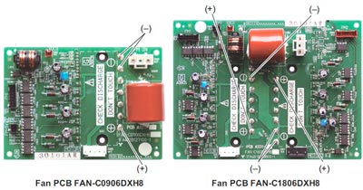
Error code P29: Compressor 1 start error (compressor block, wiring phase open, DCCT error)
Alarm conditions:
This alarm can occur at start-up and occurs if a missing phase or lock is detected and if a DCCT error occurs.
Possible causes:
Generally, this alarm occurs when the refrigerant pressure equalisation is uneven at startup or when the inverter compressor locks up, there is no phase in the inverter compressor wiring, or a DCCT error occurs. This can be seen as a startup problem that is not caused by HIC
Location:
Check the power and connector wiring.
Correction:
DCCT error (replace circuit board) or compressor error
Notes:
Use a tester to measure the voltage between the DCCT output on the back of the PCB and the earth. If the voltage is not within 2 - 3 V, the DCCT is malfunctioning.
| Meaning of the error | Current alarm for compressor with constant speed and 2 locks
| |||
| Preconditions | During operation, the compressor current exceeded 12 A for at least 30 seconds. However, this alarm is not recognised 4 seconds after the compressor has started | |||
| Possible causes |
| |||
| Priority check | 1. Compressor failure (partially locked) Problem: The current value during operation considerably exceeds the value specified above. Test: If the current for each phase is measured with a clamp meter or similar instrument, check that the current value for all phases is not high. If MG has been switched on (caution), make sure that no compressor noises occur or that the compressor does not run with a groaning noise. 2. CT circuit failure, PCB failure Check: 3. Missing power phase problem: This alarm mainly occurs when the T phase is missing. If the R phase or S phase is missing, transformer or PCB continuity problems arise. However, this may not apply in the event of a missing phase caused by a magnetic SW error. Check: There is a possibility of a magnetic SW error. Therefore, check the phase voltage in a location as close as possible to the compressor. 4. Low voltage problem: In most cases, this occurs when another constant speed compressor (including compressors in other units) or another unit is started. This also occurs when the power cables are extremely long. Test: Check the voltage between the individual phases. However, if this occurs when starting other units or compressors, an oscilloscope is required. 5. PCB error Test: Ensure that the current value measured with the clamp meter is not below the value measured with the PC or the remote control. 6. If after checking the above items the cause is still unknown, it is possible that noise is the cause of the problem. It is necessary to connect a PC or other instrument | |||
| Correction: | Replace the compressor. | |||
H02 Leistungsfaktorkorrektur-Schutz
1. Voraussetzung(en) für die Störmeldung:
- Aufrechterhaltung des Gleichspannungspegels an der Versorgung des Leistungstransistors.
- Zur Erkennung eines hohen Gleichspannungspegels nach der Gleichrichtung.
2. Ursache(n):
- Während des Starts und des Betriebs von Kühlung und Heizung, wenn die Schutzschaltung für die Leistungsfaktorkorrektur (PFC) auf der Hauptplatine des Außengeräts einen anormalen Gleichspannungspegel für die Leistungstransistoren erkennt.
- Wenn die erkannte Gleichspannung NIEDRIG ist, schaltet der Regler die Transistoren ein, um den Gleichstrompegel zu erhöhen.
- Wenn die erkannte Gleichspannung HOCH ist (391Vdc - 425Vdc), wird ein aktives LOW-Signal vom Regler gesendet, um das Relais RY-C auszuschalten.
3. Fehlersuche:
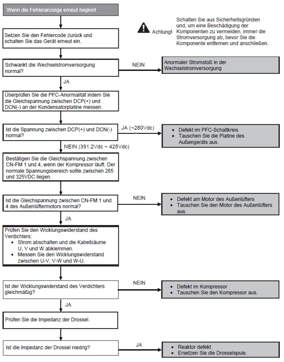
Fehlercode H20: Fehlfunktion der Wasserpumpe
Alarmbedingungen:
Wenn dieser Alarm 5 Sekunden angezeigt wird.
Mögliche Ursache :
- Betriebsstopp aufgrund eines Kurzschlusses in der Motorwicklung der Wasserpumpe.
- Betriebsstopp aufgrund eines Drahtbruchs im Wasserpumpenmotor.
- Betriebsstopp aufgrund eines Bruchs der Wasserpumpenkabel.
- Betriebsstopp aufgrund einer Störung des Wasserpumpenmotors 1PM.
- Betriebsfehler aufgrund einer fehlerhaften Leiterplatte des Innengeräts.
Korrektur:
- Ersetzen Sie die Wasserpumpe
- Ersetzen Sie die Innengerätplatine
L13 Fehler bei der Einstellung des Innengerätetyps
1. Fehlererkennungsmethode:
- Diskordanzmodell(e) zwischen Außen- und Innengerät werden erkannt.

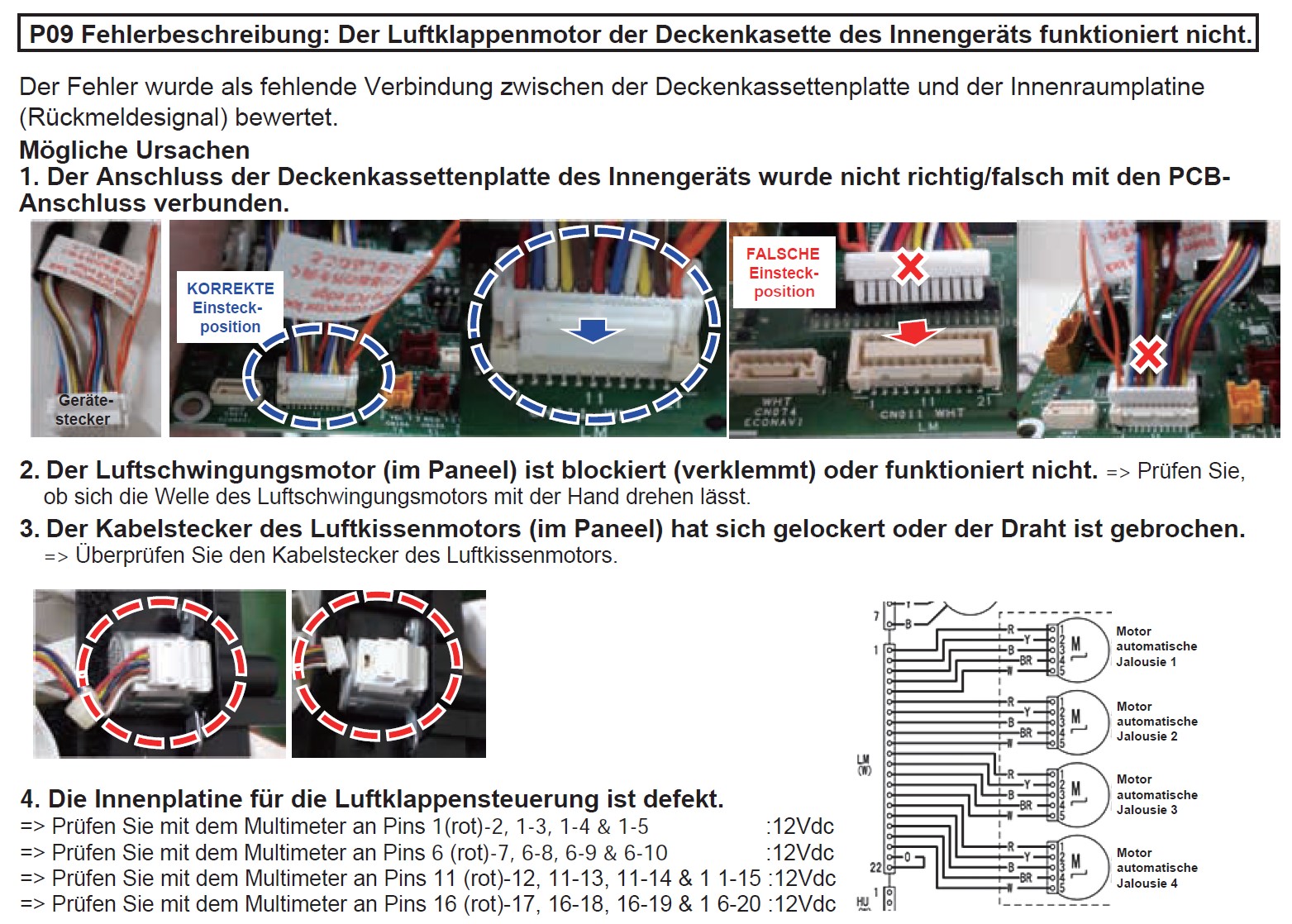
P31 Gruppensteuerungsfehler
1. Fehlererkennungsmethode
- Andere Alarme von Innengeräten innerhalb der Gruppe.

How do you recognise the alarm display of LEDs 1 and 2 on the outdoor unit control board
LED 1 shows the TYPE of the alarm:
2 flashes = Alarm P
3 flashes = Alarm H
4 flashes = Alarm E
5 flashes = Alarm F
6 flashes = alarm L
LED 2 shows the number of the alarm:
1 = 1
2 = 2
3 = 3
As an example: If the LED 1 flashes 2 times and the LED 2 17 times, the alarm indicates error P17
This is repeated continuously.
Fehlercodes für Inneneinheiten

Fehlercodes für Außeneinheiten (U-25PZ3E5, U-36PZ3E5, U-50PZ3E5, U-60PZ3E5A, U-71PZ3E5A, U-36PZH3E5, U-50PZH3E5, U-60PZH3E5)

Fehlercodes für Außeneinheiten (U-100PZ3E5, U-125PZ3E5, U-140PZ3E5, U-100PZ3E8, U-125PZ3E8, U-140PZ3E8)
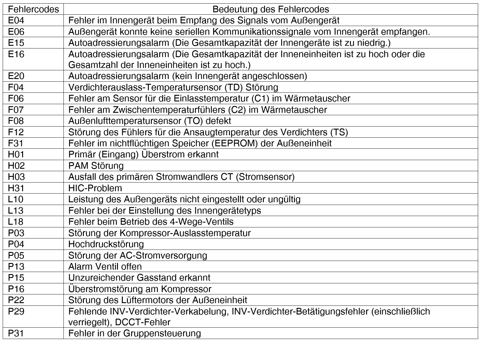
Zu finden unter: Mein Konto > Meine Auswertungen
Um Ihre Kältemittel Auswertungen beobachten zu können, finden Sie nach klicken auf "Mein Konto" ein Dropdown-Fenster mit "Meine Auswertungen". Nach einem Klick auf "Meine Auswertungen" öffnet sich eine Seite mit ""Kältemittel Auswertung". Sie können auch die Suche nutzen um die Auftragsnummer oder Artikelbezeichnung einzugeben. Sie können auch nach Datum sortieren und ein Zeitfenster der Aufträge eingeben. Mit Klick auf Filter bestätigen Sie die Suche mit Klick auf das rote Mülltonnensymbol entfernen Sie bereits gesetzte Filter.
Hier kann man zwischen 3 Ebenen Wählen- Einkäufe-Pfandgebinde-Entsorgung
Einkäufe:
Hier sehen Sie alle Kältemittel Einkäufe die sie jemals getätigt haben.
Zudem kommen sie mit Klick auf die Auftragsnummer gleich zu Ihrer getätigten Bestellung.
Pfandgebinde:
Unter Pfandgebinde finden Sie noch lagernde Kältemittelflaschen in Ihrem Betrieb.
Entsorgung
Hier sehen Sie auf einen Blick alle Kältemittel Entsorgungen die sie getätigt haben.
You can view the current status of your order at any time, as well as all previous purchases.
The order status is divided into 3 statuses such as delivered goods, deliverable goods, not yet delivered goods, which also differ in color.
How can I check my order status?
Go to my account and click → my orders. This will take you to the overview of your orders.
Click directly in the respective order for which you want to check the status.
Address management is primarily used to manage addresses and contact information. Under my addresses, you can conveniently add, save, edit, duplicate and set as default your addresses at any time.
Where can I find the address management?
Go to the arrow, to the right of your user and select → My addresses. Here you can add, save, edit, duplicate or set as default your addresses.
The comparison tool allows you to take a closer look at 3 items and select the one that meets your needs.
You can compare between:
- Photo
- manufacturer
- different technical data
- price
How does the comparison tool work?
Select the category in which you want to compare. To the right of the products, you will see blue arrows. Click on these arrows for the products you want to compare.
Finally, you need to click on the compare button on the right to enter the comparison view.
With the new filters, such as "Manufacturer", "Availability" or "Type", you can get to the product you want as quickly as possible. The filter function is already available in several categories. Select your desired category. You can apply the filter individually.
Above you can see the filter options. You can also click → show more, so you can expand all filters and filter more detailed. After you have applied the filters, your desired products will also be displayed.
Reset filter
Do you no longer want to narrow down your search results? Then you can deactivate all filters with the button "Cancel all".
Whether news, existing shopping carts, open offers, orders, rental bottles and much more... Everything at a glance! The administration of your own employees allows you to flexibly design the rights on mySCHIESSL - so you can define who is allowed to do what and how (view prices, orders, stock, invoice download, etc.) true to the department.
The product finder helps you to quickly find the right compressor or condensing unit. That means you have the possibility to define the refrigerant and the application type in the categories compressors and condensing units and also to narrow down the capacity.
How to use the product finder?
When you are in the Compressors and Units category, you can click on one of the buttons shown above to access either the Compressors category or the Condensing Units category. In both of these categories you can use the product finder.First select your desired refrigerant. Then specify the type of application you want. Limit the capacity range by defining the from and to value.
Finally, you can filter the specified products, for example, if you are looking for a specific manufacturer, etc.. In this way, you will be shown exactly those items that meet your requirements. If you want to remove the filters, click on Reset all filters.
Click here for step-by-step instructions: Product finder
The QR code scanner makes it easier for you to search for products. We want you to get to the products you want as quickly as possible. The QR codes make your work easier. Already downloaded CR codes are saved, so you don't have to download the QR code every time again.
Where can I find the QR code scanner?
The QR codes can be downloaded on the product (single QR codes), under my orders (multiple QR codes) or under the favorites list and directly in the shopping cart (multiple QR codes) as a zip file.
In the search mode you can easily and quickly, article and manufacturer numbers and keywords used to search for articles. The respective availability and quantity per storage location can be called up at any time in our transparent company.
Configure your own brochure as a PDF file for all items. You have a flexible choice of information which will be displayed on your own brochure. Choose product image, product description, accessories/spare parts, technical data and dimensional drawings, scope of delivery, among others.
How to create a PDF brochure / flyer?
Add your desired items to your shopping cart. Go under shopping carts and scroll all the way down. On the right is a button "Options", here you can click → create your own PDF brochure / flyer.
You can select product image, product description, accessories / spare parts, technical data and dimensional drawings, as well as price display.Thus you have a flexible choice of information to display in your brochure / flyer.
Configure your own datasheet as a PDF file for all items. You have a flexible choice of information which will be displayed on your own product data sheet. Select product image, product description, accessories/spare parts, technical data and dimensional drawings, among others. Pricing is also entirely up to you (show without prices, show gross price only, or store an individual price).
Accessories, technical data, downloads, dimensional drawings or even alternative articles can be conveniently called up and read. Thanks to our extensive database, information about previous and successor products as well as accessory items can also be called up. - There is no easier way to shop online!
By connecting mySCHIESSL to the merchandise management system or to the craftsmen's software via these established interfaces, you immediately reduce the manual effort of the ordering process and all subsequent processes, as there is no need for double entry in the merchandise management system.
What are the advantages of interfaces?
By connecting mySCHIESSL to the merchandise management system or to the craftsmen's software via these established interfaces, you immediately reduce the manual effort of the ordering process and all subsequent processes, since no double entry has to be made in the merchandise management system.
Click for a detailed explanation: Interfaces
Retrieving the fault code with the cable remote control

If a fault occurs, CHECK flashes in the display (see figure above).
 When the CHECK button is pressed, an error code from F15 to F44 now appears in the timer field. The air conditioner number appears instead of the set temperature:
 While the fault is displayed, press the TIMER SET button. The fault code is now replaced by an additional code that provides more detailed information on the previously mentioned fault:
Please note:
For single operation, "01" appears as the air conditioner number. In the case of a group set-up, however, a different number can appear. By pressing the "A / C No." the air conditioner number can be called up.
Display of previous fault codes
If the CHECK display is not flashing, press the CHECK button for 5 seconds to display the last or second last fault. You can toggle between the last and second last fault by pressing the TIMER UP or DOWN
  buttons.
Display the last fault code: 1F15 - 1F44
Display the second last fault code: 2F15 - 2F44
The additional code is also called up in this case with the TIMER SET button.
Press the CHECK button again to return to the normal display.
 Press for 5 seconds
the CHECK button:
 Press for additional codes
the TIMER SET button
Retrieving the fault code with the infrared remote control

When a fault occurs, the TIMER LED flashes on the infrared receiver. To query the fault code, the list of fault codes must be run through with the remote control until the indoor unit beeps to indicate that the corresponding fault code has been found. To do this, proceed as follows:
- press the button again. "F 00:00" appears.
- The keys are used to scroll through the digits of the first fault code from "F 0" to "F 9”.
As soon as the number of the first digit matches that of the fault code, a beep sounds in the indoor unit. - The search for the first digit is now completed by pressing the SET button and the cursor jumps to the second digit.
- Steps 3 to 4 are repeated for the second and third digits.
The search for the fault code is completed as soon as a beep sounds at the fourth digit after pressing the buttons or in the indoor unit. The complete fault code can now be read from the display.
F11 4-Wege-Ventil-Schaltstörung
Voraussetzung(en) für die Störmeldung:
- Wenn der Wärmetauscher im Innenraum während des Heizens kalt ist (außer bei Enteisung) oder wenn der Wärmetauscher im Innenraum währen des Kühlens und des Kompressorbetriebs heiß ist, wird das 4-Wege-Ventil als Störung erkannt.
Ursache(n):
- Thermistor des inneren Wärmetauschers
- Störung des 4-Wege-Ventils
Fehlersuche:
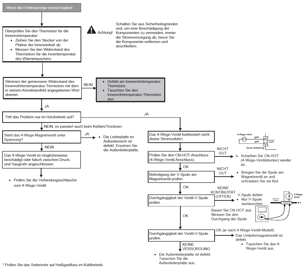
F16-01 Louvre switch (ceiling-mounted units)
| Fault description | Louvre switch (ceiling-mounted units) |
| Preconditions for fault message | The fault occurs when the louvre limit switch does not output any switching signals, even though the louvre motor is activated. |
| Possible causes |
|
| Detection of the fault | See above under “Preconditions for fault message". |
F17 Frostschutz der Standby-Geräte im Innenraum
Voraussetzung(en) für die Störmeldung:
- Wenn der Unterschied zwischen Ansauglufttemperatur im Innenbereich und der Rohrtemperatur im Innenbereich über 10°C liegt oder die Temperatur der Innenraumleitung unter -1,0°C liegt.
- Bemerkung: Wenn das Standby-Innegerät einfriert, überträgt das Außengerät den Fehlercode F17 an das entsprechende Innengerät und H39 an andere Innengeräte.
Ursache(n):
- Falscher Anschluss der Verdrahtung
- Defekter Sensor
- Fehlerhaftes Expansionsventil
Fehlersuche:
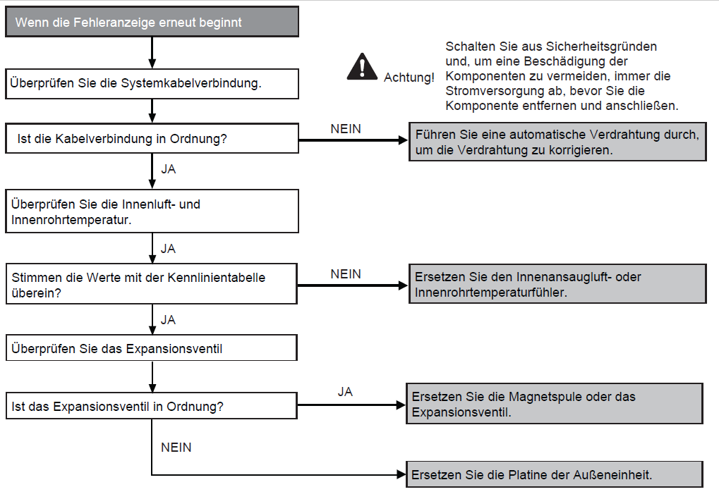
F20-01 Indoor unit intake temperature sensor (room temperature sensor)
| Fault description | Indoor unit intake temperature sensor (room temperature sensor) |
| Preconditions for fault message |
|
| Possible causes |
|
| Detection of the fault | See above under “Preconditions for the fault message". |
F20-02 Remote control temperature sensor
| Fault description | Remote control temperature sensor |
| Preconditions for fault message |
|
| Possible causes | Sensor error in the cable remote control. |
| Detection of the fault | See above under “Preconditions for fault message". |
F21-01 Indoor unit heat exchanger temperature sensor
| Fault description | Indoor unit heat exchanger temperature sensor |
| Preconditions for fault message |
|
| Possible causes |
|
| Detection of the fault | See above under “Preconditions for the fault message". |
F26-01Remote data transmission
| Description of fault | Remote data transmission |
| Preconditions for fault message | No response from the remote control for 3 minutes. |
| Possible causes |
|
| Detection of the fault | See above under “Preconditions for the fault message”. |
F30-01 System problem
| Description of fault | System problem |
| Preconditions for fault message | The performance of the indoor unit (or the sum of the indoor units) does not match the outdoor unit (the total output of the connected indoor units is below the minimum power limit or above the maximum power limit of the outdoor unit). |
| Possible causes | Too many indoor units or indoor unit (s) of incorrect power connected. |
| Detection of the fault | Immediate |
F30-02 Phase open or reversed
| Description of the fault | Phase open or reversed |
| Preconditions for fault message | The system detects a phase that does not exist or is inverted. |
| Possible causes |
|
F31-01 Suction pressure shutdown
| Description of the fault | Suction pressure shutdown |
| Preconditions for fault message |
|
| Possible causes |
|
F31-02 High pressure shutdown
| Description of the fault | High pressure shutdown |
| Preconditions for fault message | The heat exchanger temperature is above the limit, which indicates an increase in high pressure. |
| Possible causes |
|
| Detection of the fault | The heat exchanger temperature must be above the limit three times within 30 minutes for one minute each. |
F32-06 Switch valve
| Description of the fault | Switch valve |
| Preconditions for fault message | When the compressor is running, the indoor unit heat exchanger is too cold (<5°C) for 5 minutes in heating mode (except when defrosting) or too warm in cooling mode (>45°C). |
| Possible causes |
|
| Detection of the fault | The above preconditions are met three times within 30 minutes. |
F32-08 Freezing of the indoor unit heat exchanger
| Description of the fault | Freezing of the indoor unit heat exchanger |
| Preconditions for fault message | The temperature of the indoor unit heat exchanger is below a certain value for a certain period. |
| Possible causes |
|
F32-09 Inverter protection (DC overcurrent
| Inverter protection (DC overcurrent) | Preconditions) |
| for fault message | Inverter DC overcurrent signals are detected during start-up and in cooling and heating mode. |
| Possible causes |
|
| Detection of the fault |
|
F32-10 Refrigeration problem
| Description of the fault | Refrigeration problem |
| Preconditions for fault message | One of the following conditions must be met within seven minutes of the compressor starting up in cooling mode:
|
| Possible causes |
|
| Detection of the fault | See under “Preconditions for fault message”. |
F32-03 Inverter protection (low DC voltage)
| Description of the fault | Inverter protection (low DC protection) |
| Preconditions for fault message | DC voltage <180 V in 40 ms after tightening RY_AC (RY_PWR). |
| Possible causes |
|
| Detection of the fault | Immediate. |
F32-04 Overheating protection of the power transistor (IPM)
| Description of the fault | Overheating protection of the power transistor (IPM) |
| Preconditions for fault message | Elevated temperature of the power transistor module (IPM) (5 Sec. > 95°C). |
| Possible causes |
|
| Detection of the fault | 4 occurrences within 30 minutes. |
F32-05 Compressor overcurrent protection
| Description of the fault | Compressor overcurrent protection |
| Preconditions for fault message | The current consumption is exceptionally high during compressor operation. |
| Possible causes |
|
| Detection of the fault | 3 occurrences within 30 minutes. |
F32-06 Hot gas temperature protection
| Description of the fault | Hot gas temperature protection |
| Preconditions for fault message | In cooling or heating mode, the hot gas temperature exceeds 110°C, the compressor is switched off. If it falls below 105°C, the compressor starts again after 3 minutes. |
| Possible causes |
|
| Detection of the fault | 3 occurrences within 60 minutes. |
F32-08 Inverter protection (reactive current compensation)
| Description of the fault | Inverter protection (reactive current compensation) |
| Preconditions for fault message | Incorrect signals in the reactive current compensation circuit (PFC circuit). |
| Possible causes |
|
| Detection of the fault | The problem has existed for three minutes. |
F32-09 Inverter protection (DC overcurrent
| Description of the fault | Inverter protection (DC overcurrent) |
| Preconditions for fault message | Inverter DC overcurrent signals are detected during start-up and in cooling and heating mode. |
| Possible causes |
|
| Detection of the fault |
|
F32-10 Incorrect compressor speed
| Description of the fault | Incorrect compressor speed |
| Preconditions for fault message | The compressor speed does not correspond to the speed signal. |
| Possible causes |
|
| Detection of the fault | 4 occurrences within 20 minutes. |
F35 DC fan motor blocked.
Priority check: DC fan motor
No obvious fault: Please contact one of our technicians
F40-01 Outside temperature sensor
| Description of the fault | Outside temperature sensor |
| Preconditions for fault message | A temperature of <-33.4°C or > 124°C is determined for 5 seconds. |
| Possible causes |
|
F40-11 Compressor suction gas temperature sensor
| Description of the fault | Compressor suction gas temperature sensor |
| Preconditions for fault message | A temperature of <-50.5°C or > 103.7°C is detected for 5 seconds. |
| Possible causes |
|
F40-21 Compressor suction gas temperature sensor
| Description of the fault | Compressor suction gas temperature sensor |
| Preconditions for fault message | A temperature of <-50.5°C or > 103.7°C is detected for 5 seconds. |
| Possible causes |
|
F40-31 Defrost temperature sensor
| Description of the fault | Defrost temperature sensor |
| Preconditions for fault message | A temperature of <-50.5°C or > 103.7°C is detected for 5 seconds. |
| Possible causes |
|
F40-51 Compressor hot gas temperature sensor
| Description of the fault | Compressor hot gas temperature sensor |
| Preconditions for fault message | With the compressor running (except start-up), a temperature <-4.5°C or > 201.8°C is detected for 5 seconds. |
| Possible causes |
|
F41 -02 High pressure switch open
| Description of fault | High pressure switch open |
| Preconditions for fault message | The high pressure switch is open for one minute while the compressor is stopped. |
| Possible causes |
|
F41 - 12 Low pressure switch -open
| Description of the fault | Low pressure switch (Not Inverter) |
| Preconditions for fault message | The low pressure switch is open for one minute while the compressor is stopped. |
| Possible causes |
|
F42 Transformer
| Description of the fault | Transformer in outdoor unit is open |
| Preconditions for fault message | The power consumption is too low for 60 seconds after the compressor starts. |
| Possible causes |
|
| Detection of the fault | 1 minute after compressor start:
|
F44: Inverter protection
| Description of the fault | Inverter protection (Power transistor module temperature sensor) |
| Preconditions for fault message | The temperature sensor in the circuit of the power transistor module determines an elevated temperature. |
| Possible causes: | Faulty outdoor unit circuit board. |
F90
Voraussetzung(en) für die Störmeldung:
- Aufrechterhaltung des Gleichspannungspegels für den Leistungstransistor.
- Zur Erkennung eines hohen Gleichspannungspegels nach der Gleichrichtung.
Ursache(n):
- Während des Starts und des Heiz- und Kühlbetriebs, wenn die Schutzschaltung für die Leistungsfaktorkorrektur auf der Hauptplatine des Außengeräts eine anormale Gleichspannungspegel für die Leistungstransistoren erkennt.
- Wenn die erkannte Gleichspannung NIEDRIG ist, schaltet der Regler die Transistoren ein, um den Gleichstrompegel zu erhöhen.
- Wenn die erkannte Gleichspannung HOCH ist (391V DC - 425 V DC), sendet der Regler ein akrives NIEDRIG-Signal, um das Relais RY-C auszuschalten.
Fehlersuche:

F91
Voraussetzung(en) für die Störmeldung:
- Der Eingangsstrom ist niedrig, während der Verdichter mit einer höheren als der eingestellten Frequenz läuft.
Ursache(n):
- Gasmangel
- 3-Wege-Ventil geschlossen
Fehlersuche:
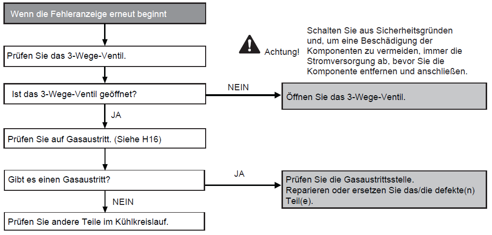
F93
Voraussetzung(en) für die Störmeldung:
- Die falsche Kompressor Drehzahl wird duch Überprüfung des Verdichterbetriebszustands über den Positionserkennungskreis erkannt.
Ursache(n):
- Verdichterklemme nicht angeschlossen
- Defekte Außenleiterplatte
- Defekter Verdichter
Fehlersuche:
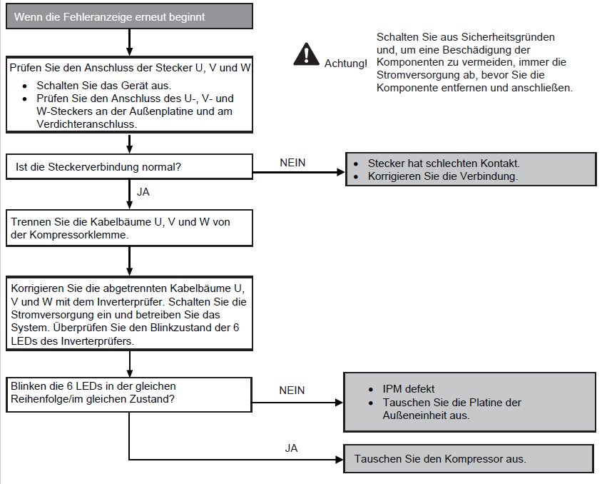
F95
Voraussetzung(en) für die Störmeldung:
- Während des Kühl- oder Soft-Dry-Betriebs, wenn der Wärmetauscher des Außengeräts vom Thermistor des Außengeräts eine hohe Temperatur erfasst.
Ursache(n):
- Kurzschluss des heißen Auslassluftstrom
- Defekt am Motor des Außenlüfters
- Defekter Thermistor des Außenwärmetauschers
- Defekt an der Platine des Außengeräts
Fehlersuche:
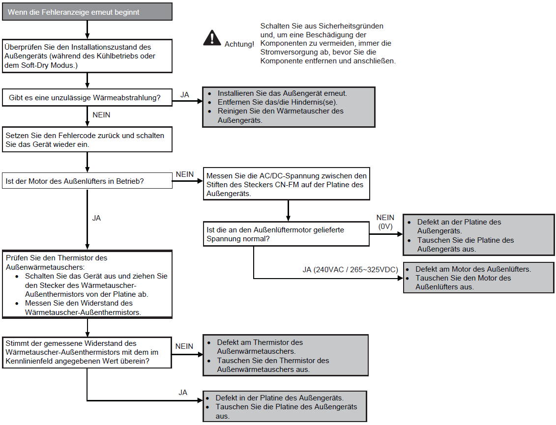
F96
Voraussetzung(en) für die Störmeldung:
- Während des Kühl- und Heizbetriebs, wenn die IPM-Temperaturdaten (100°C) vom IPM-Temperatursensor erfasst werden.
- Nur bei Multi-Modellen:
- Überhitzung des Kompressors: Während des Kühl- und Heizbetriebs, wenn der Verdichter OL aktiviert wird.
- Überhitzung des Kühlkörpers: Während des Kühl- und Heizbetriebs, wenn der Temperatursensor des Kühlkörpers eine Temperatur von 90°C feststellt.
Ursache(n):
- Kurzschluss des heißen Auslassluftstroms
- Defekt am Außenlüftermotor
- Defekt am internen Schaltkreis des IPM
- Defekter IPM-Temperatursensor
- Nur bei Multi-Modellen:
- Kompressor-OL-Stecker hat schlechten Kontakt
- Verdichter OL defekt
Fehlersuche:
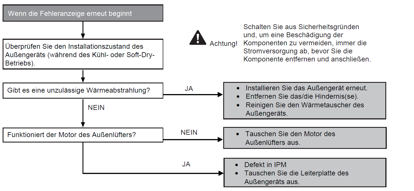
F97
Voraussetzung(en) für die Störmeldung:
Während des Kühl- und Heizbetriebs, wenn die Temperaturdaten des Verdichterbehälters (112°C) vom Verdichterbehältertemperatursensor erfasst werden.
Ursache(n):
- Defekter Temperatursensor im Verdichterbehälter
- 2/3-Wegeventil geschlossen
- Kältemittelmangel (Kältemittelleckage)
- Defekte Leiterplatte des Außengeräts
Fehlersuche:
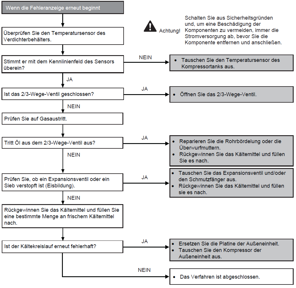
F98
Voraussetzung(en) für die Störmeldung:
Während des Kühl- und Heizbetriebs, wenn ein Eingangsüberstrom (X-Wert in Total Running Current Control) durch Überprüfung des vom Stromwandler (CT) erfassten Eingangsstromwerts bei laufendem Kompressor erkannt wird.
Ursache(n):
- Überschüssiges Kältemittel.
- Defekte Leiterplatte des Außengeräts.
Fehlersuche:
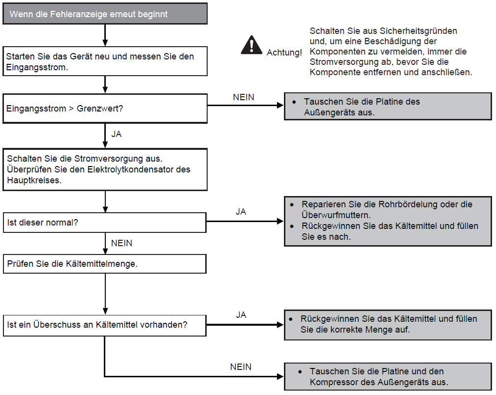
F99
Voraussetzung(en) für die Störmeldung:
Während des Starts und des Betriebs von Kühlung und Heizung, wenn der interne DC-Spitzenwert-Erkennungsschaltkreis im Außenbereich DC-Spitzenwertdaten vom Wechselrichter empfängt.
Ursache(n):
- DC-Stromspitze aufgrund eines Verdichterausfalls.
- Gleichstromspitze durch defekte(n) Leistungstransistor(en).
- Gleichstromspitze aufgrund einer defekten Leiterplatte des Außengeräts.
- Gleichstromspitze aufgrund eines Kurzschlusses.
Fehlersuche:
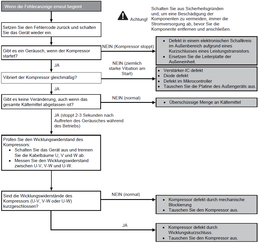
H11
Voraussetzung(en) für die Störmeldung:
- Während der Inbetriebnahme und des Heiz- und Kühlbetriebs wird geprüft, ob die vom Außengerät empfangenen Daten bei der Signalübertragung des Innengeräts normal sind.
Ursache(n):
- Defekte Leiterplatte des Innengeräts
- Defekte Leiterplatte des Außengeräts
- Signalübertragungsfehler Innengerät-Außengerät aufgrund eines Verdrahtungsfehlers
- Signalübertragungsfehler Innengerät-Außengerät aufgrund eines Drahtbruchs in den Verbindungsleitungen zwischen Innen- und Außengerät
Fehlersuche:
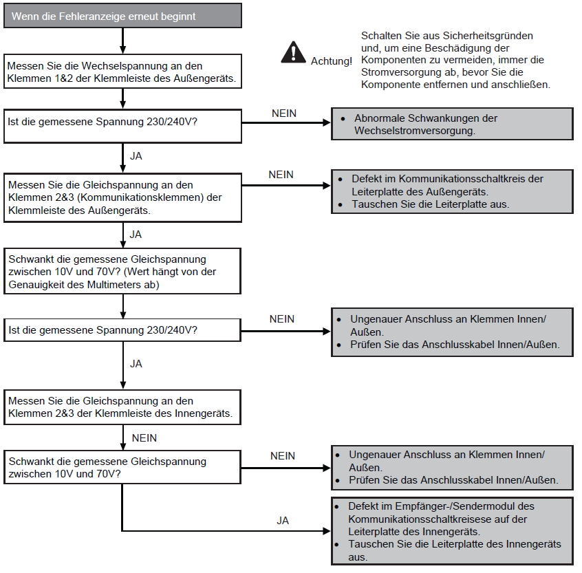
H12
Voraussetzung(en) für die Störmeldung:
- Während der Inbetriebnahme erscheint ein Fehlercode, wenn verschiedene Typen von Innen- und Außengeräten zusammengeschaltet sind.
Ursache(n):
- Falsche Modelle zusammengeschaltet
- Falsche Innengerät- oder Außengerät-Leiterplatten montiert
- Leiterplatten des Inne- oder Außengeräts sind defekt
- Signalübertragungsfehler des Innen- und Außengeräts aufgrund falscher Verdrahtung
- Signalübertragungsfehler des Innen- und Außengeräts aufgrund eines Bruchs von Draht 3 in den Verbindungskablenz zwischen Innen- und Außengerät
Fehlersuche:
H14
Voraussetzung(en) für die Störmeldung:
- Während der Inbetriebnahme und des Kühl- und Heizbetriebs werden die vom Raumlufttemperaturfühler erfassten Temperaturen zur Beestimmung von Sensorfehlern verwendet.
Ursache(n):
- Fehlerhafte Steckerverbindung
- Defekter Sensor
- Defekte Leiterplatte
Fehlersuche:
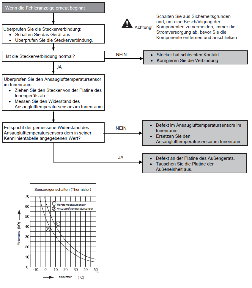
H15
Voraussetzung(en) für die Störmeldung:
- Während der Inbetriebnahme und des Kühl- und Heizbetriebs werden die vom Außenverdichter-Temperatursensor erfassten Temperaturen zur Bestimmung von Sensorfehlern verwendet.
Ursache(n):
- Fehlerhafte Steckerverbindung
- Defekter Sensor
- Defekte Leiterplatte
Fehlersuche:
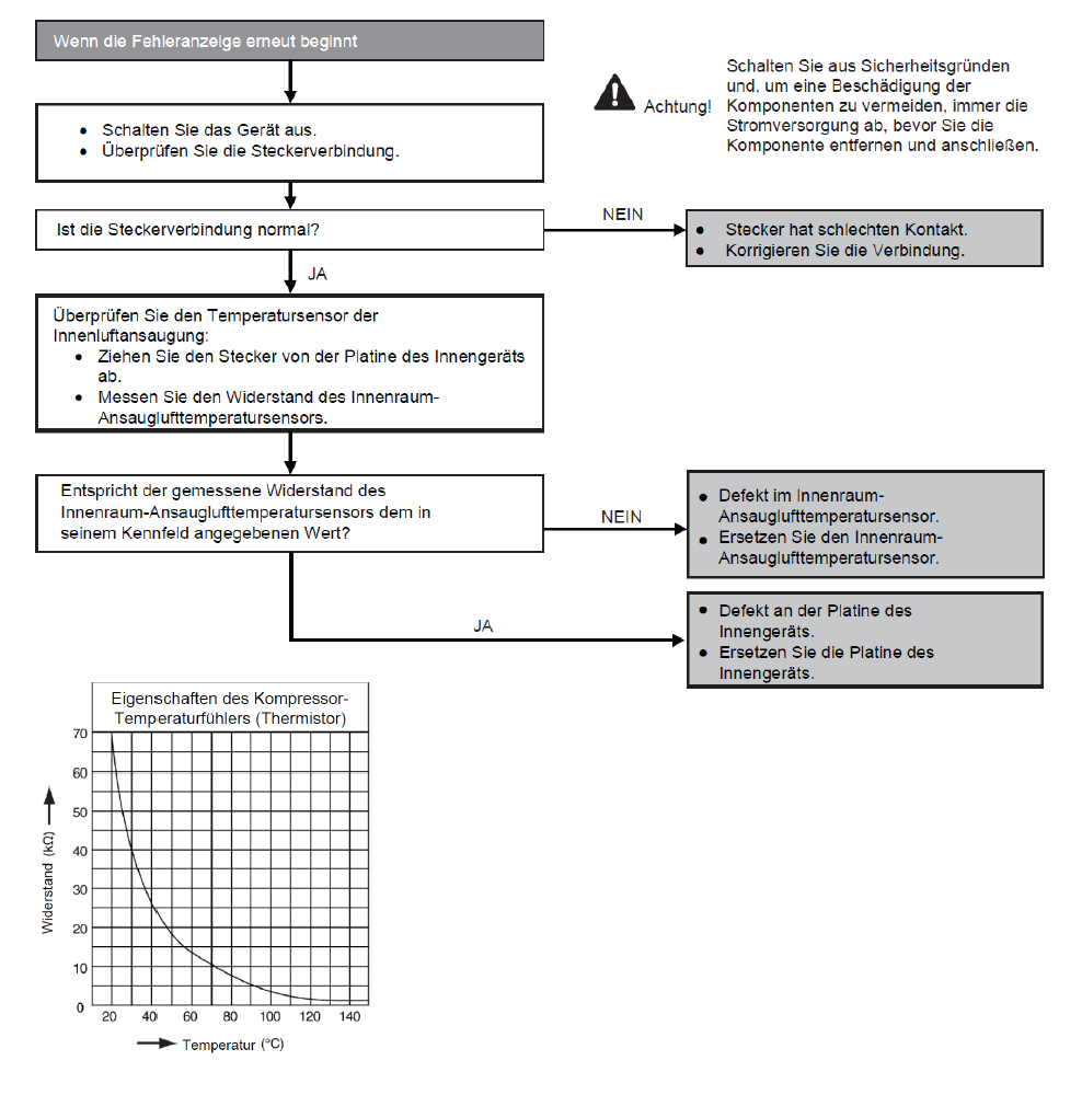
H16
Voraussetzung(en) für die Störmeldung:
- Ein vom Stromwandler erfasste Eingangsstrom liegt unter dem Schwellenwert, wenn der Verdichter 3 Minuten Lang bei einem bestimmten Frequenzwert betrieben wird.
Ursache(n):
- Gasmangel
- Defekter Stromwandler
- Defekte Außenplatine
Fehlersuche:

H19
Voraussetzung(en) für die Störmeldung:
- Die vom Hall-Sensor während des Betriebs des Lüftermotors erfasste Drehzahl wird verwendet, um einen abnormalen Lüftermotor zu bestimmen.
Ursache(n):
- Kurzschlusse in der Wicklung des Lüftermotors
- Drahtbruch innerhalb des Lüfterrmotors
- Kabelbruch in der Lüftermotorleitung
- Fehlfunktion des Hall-Sensors
- Defekte Innengeräteplatine
Fehlersuche:
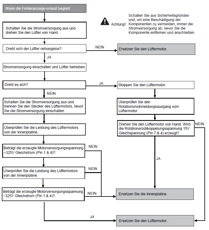
H21: Float switch in the indoor unit
Priority check: Float switch
Possible causes:
- Condensate pump clogged or no slope
- Faulty condensate pump (CN-DRMTR).
- Float switch not connected (CN-TH2, connections 1 and 2 for cassettes and CN-FSW, Connections 1 and 3 for duct units).
- Float switch defective (blocked in the open position).
- Faulty indoor unit ciruit board.
- Fan motor mechanically blocked.
To check and remedy see figure.

H23
Voraussetzung(en) für die Störmeldung:
- Während der Inbetriebnahme und des Kühl- und Heizbetriebs werden die vom Innenraum-Wärmetauschertemperatursensor erfassten Temperaturen zur Bestimmung von Sensorfehlern verwendet.
Ursache(n):
- Fehlerhafter Anschluss des Steckers
- Defekter Sensor
- Defekte Leiterplatte
Fehlersuche:

H24
Voraussetzung(en) für die Störmeldung:
- Während der Inbetriebnahme und des Heiz- und Kühlbetriebs werden die vom Temperatursensor des Innenraum-Wärmetauschers-Temperatursensor erfassten Temperaturen zur Bestimmung von Sensorfehlern verwendet.
Ursache(n):
- Fehlerhafter Anschluss des Steckers
- Defekter Sensor
- Defekte Leiterplatte
Fehlersuche:
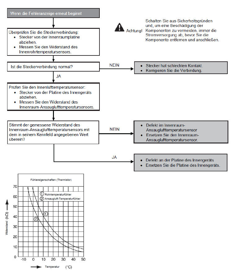
H25 E-ion power module malfunction
Priority check:
- Circuit board indoor unit
- e-ion power module
Possible causes:
- Faulty e-ion module (high-voltage generator for positive charging of the filters).
- Faulty circuit board.
- Faulty connection or wiring (open or short-circuited).
For checking and rectification see figure.
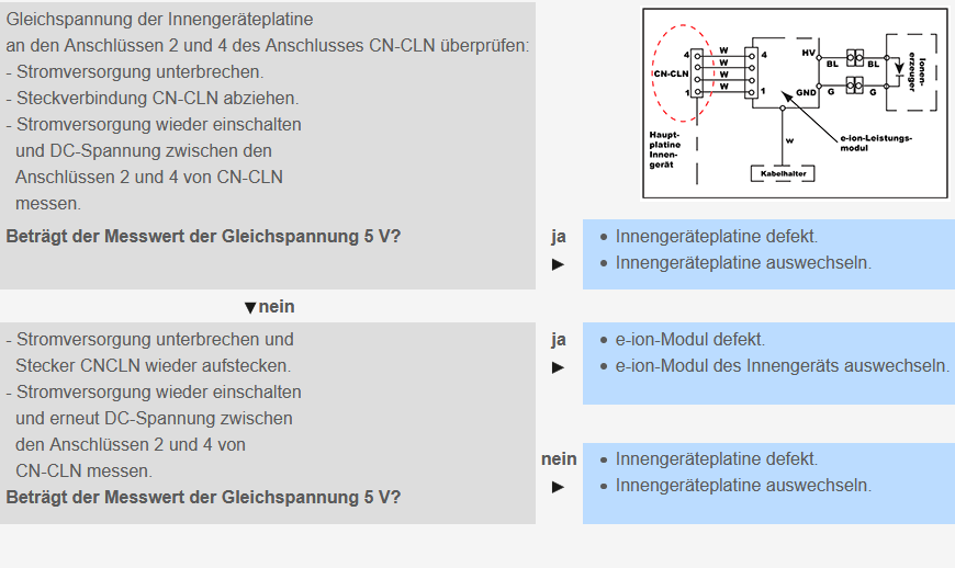
H26 Air ioniser fault
Priority check:
- Indoor unit circuit board
- Ioniser
Possible causes:
- Faulty air ioniser circuit.
- Faulty plug connection.
- Faulty circuit board.
To check and rectify see picture.
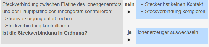
H27
Voraussetzung(en) für die Störmeldung:
- Während der Inbetriebnahme und des Heiz- und Kühlbetriebs werden die vom Außenlufttemperatursensor erfassten Temperaturen zur Bestimmung von Sensorfehlern verwendet.
Ursache(n):
- Fehlerhafte Steckerverbindung
- Defekter Sensor
- Defekte Leiterplatte
Fehlersuche:
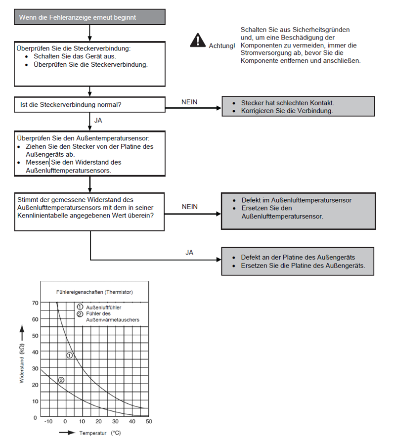
H28
Voraussetzung(en) für die Störmeldung:
- Während der Inbetriebnahme und des Heit- und Kühlbetriebs werden die vom Außenrohrtemperatursensor erfassten Temperaturen zur Bestimmung von Sensorenfehlern verwendet.
Ursache(n):
- Fehlerhafte Steckerverbindung
- Defekter Sensor
- Defekte Leiterplatte
Fehlersuche:
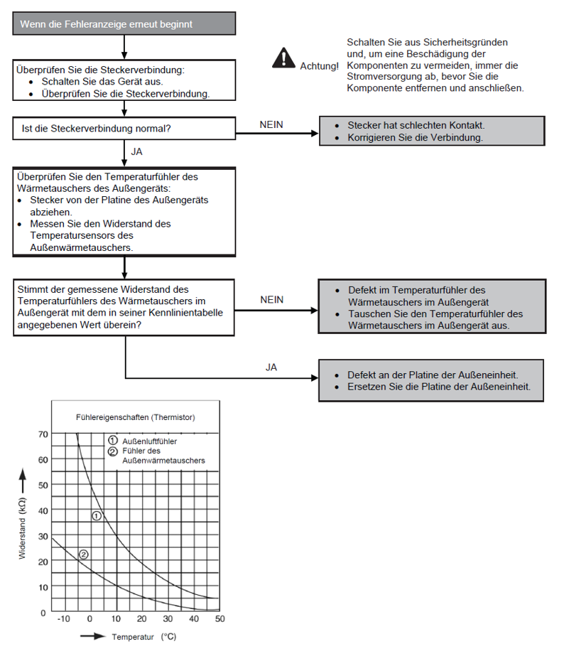
H30
Voraussetzung(en) für die Störmeldung:
- Während der Inbetriebnahme und des Heiz- und Kühlbetriebs werden die vom Außenlufttemperatursensor erfassten Temperaturen zur Bestimmung von Sensorfehlern verwendet.
Ursache(n):
- Fehlerhafte Steckerverbindung
- Defekter Sensor
- Defekte Leiterplatte
Fehlersuche:
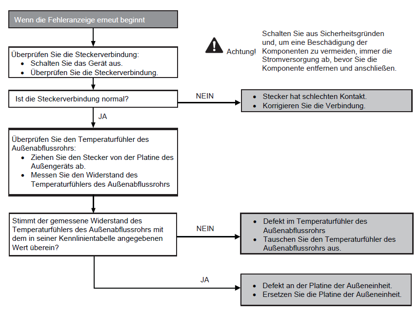
H32
Voraussetzung(en) für die Störmeldung:
- Während der Inbetriebnahme und des Heiz- und Kühlbetriebs werden die vom Außentemperatursensor des Wärmetauschers erfassten Temperaturen zur Bestimmung von Sensorfehlern verwendet.
Ursache(n):
- Fehlerhafte Steckerverbindung
- Defekter Sensor
- Defekte Leiterplatte
Fehlersuche:
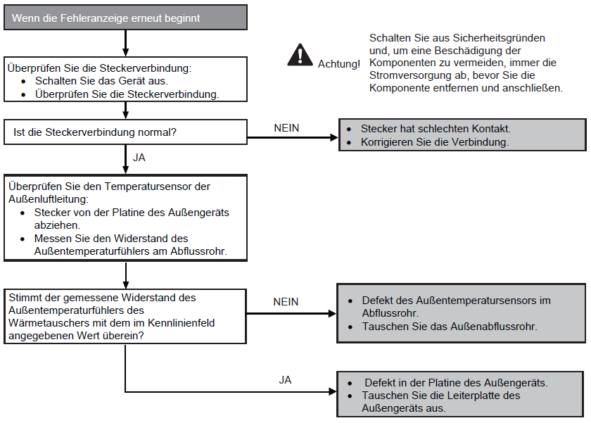
H33
Voraussetzung(en) für die Störmeldung:
- Die Versorgungsspannung wird durch die Innen-/Außenübertragung für ihren Bedarf erkannt.
Ursache(n):
- Falsche Modelle zusammengeschaltet
- Falsche Platiten für Innen- und Außengerät verwendet
- Defekte Platine des Innen- oder Außengeräts
Fehlersuche:

H34
Voraussetzung(en) für die Störmeldung:
- Während der Inbetriebnahme und des Heiz- und Kühlbetriebs werden die vom Außentemperatursensor des Kühlkörpers erfassten Temperaturen zur Bestimmung von Sensorfehlern verwendet.
Ursache(n):
- Fehlerhafte Steckerverbindung
- Defekter Sensor
- Defekte Leiterplatte
Fehlersuche:
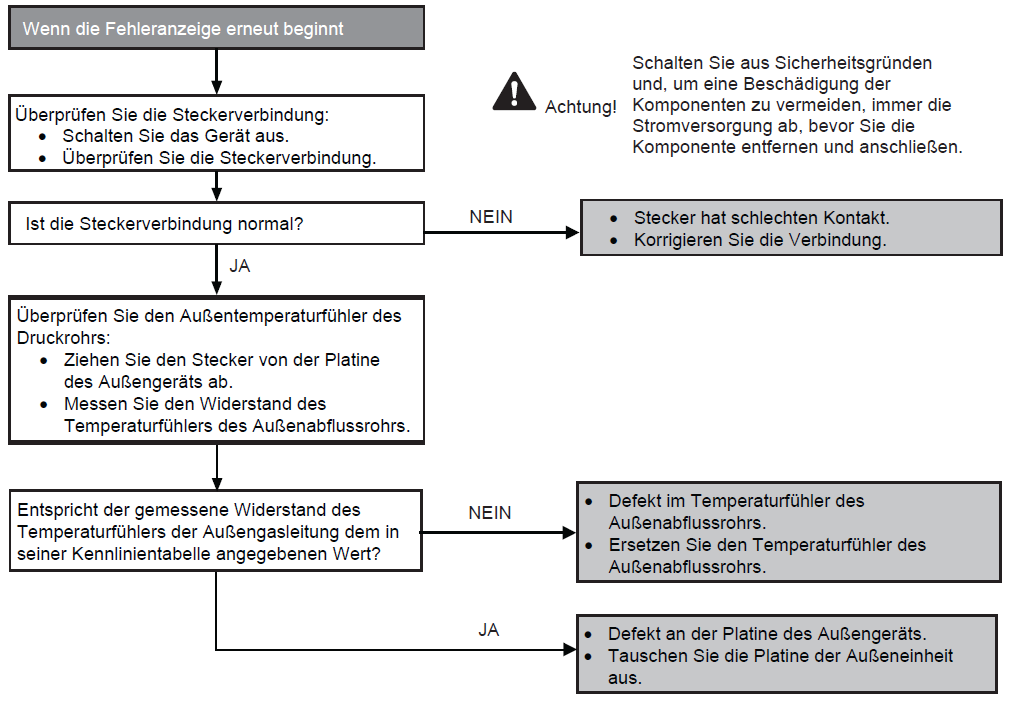
H36
Voraussetzung(en) für die Störmeldung:
- Während der Inbetriebnahme und des Heiz- und Kühlbetriebs werden die vom Gasaußentemperatursensor erfassten Temperaturen zur Bestimmung von Sensorfehlern verwendet.
Ursache(n):
- Fehlerhafte Steckerverbindung
- Defekter Sensor
- Defekte Leiterplatte
Fehlersuche:

H37
Voraussetzung(en) für die Störmeldung:
- Während der Inbetriebnahme und des Heiz- und Kühlbetriebs werden die vom Flüssigkeits-Temperaturfühler des Außengerät erfassten Temperaturen zur Bestimmung von Sensorfehlern verwendet.
Ursache(n):
- Fehlerhafte Steckerverbindung
- Defekter Sensor
- Defekte Leiterplatte
Fehlersuche:
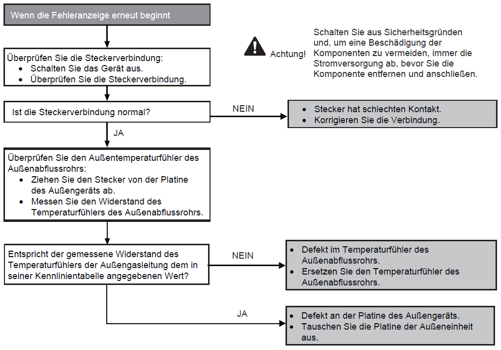
H97
Voraussetzung(en) für die Störmeldung:
- Die vom Hall-Sensor während des Betriebs des Lüftermotors erfasste Drehzahl wird verwendet, um einen defekten Lüftermotor zu bestimmen.
Ursache(n):
- Kurzschluss in der Wicklung des Lüftermotors
- Drahtbruch im Lüftermotor
- Kabelbruch in der Lüftermotorleitung
- Fehlfunktion des Hall-Sensors
- Defekte Leiterplatte des Außengeräts
Fehlersuche: